Printed in Germany / M-MT-BOS
• Edition 11.99 • # 231 763
22 … 112
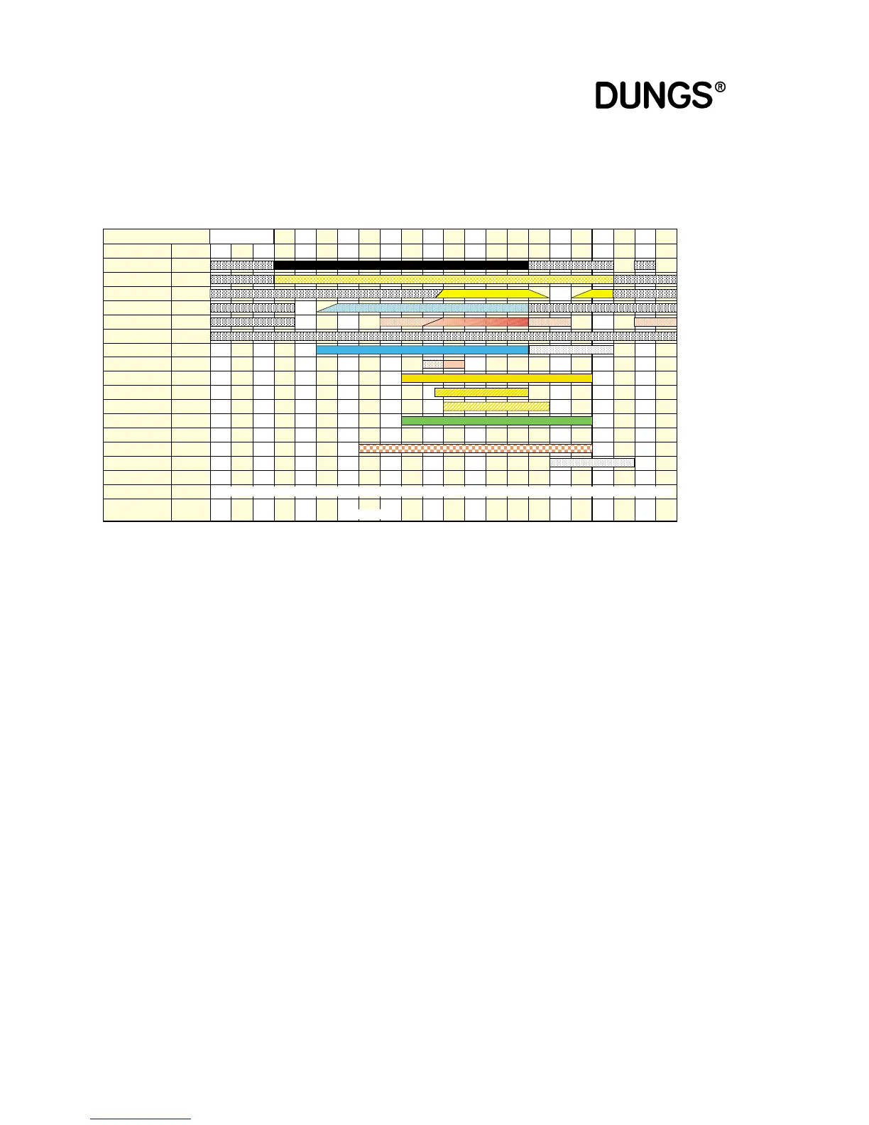
Time diagram
Gas firing, electronic
modulation
Time diagrams for MPA22 gas burner, electronic modulation
Definitions of individual states
Start-up tests Processor and program memory test/move servomotor to reference point
State 01 Start-up decision (heating request issued)
State 02 Idle state check, blower
State 03 Blower start-up
State 04 Pre-ventilation / move servomotor gas over full rotational range
State 05 Pre-ventilation / energize and test watchdog
State 06 Pre-ventilation / move servomotor gas to ignition position
State 07 Move servomotor air to ignition position
State 08 Pre-ignition (depending upon parameters)
State 09 Start-up safety period
State 10 Stabilising time
State 11 Move servomotor from ignition point to operating characteristic
State 12 Operation
State 13 Evacuate VPS valve space / (postventilation)
State 14 Test time Y2 / (remaining postventilation time)
State 15 Fill VPS valve space / (remaining postventilation time)
State 16 Test time Y3 / (remaining postventilation time)
State 17 Remaining postventilation time
State 18 Restart lockout time / wait time loop for gas fail-safe function
State 20 Start-up wait state (standby)
State 21 Postventilation before error
Footnotes:
1* The blower runs during the leakage test until the postventilation period elapses. The servomotor air then enters
standby state.
2* The pre-ignition cycle is started 0, 1 or 2 s before the start-up safety period commences, depending on the setting
in the EEPROM.
3* Valve Y2 (SV) always opens 1s before the start-up safety period commences so the GWmin can detect the
presence of gas pressure.
4* After a controlled shut-down a leakage test is performed on the valves, provided the VPS is active. The VPS flag
is then set to „valid“. If the VPS flag is invalid, e.g. after a power outage or safety shut-down in state 08 to 16, the
leakage test is performed before the main valves are opened.
Start and controlled shut-down with flame and active valve proving system
Test already performed at last controlled shut-down
Start-up tests
01 02 03 04 05 06 07 08 09 10 11 12 13 14 15 16 17 18 20
State number
Display
Closed-loop
control sequence
GW max
GW min
Air pressure switch
Flame
GW VPS
Blower motor
Ignition
Valve Y1
Valve Y2
Valve Y3
Operation
Fault
Watchdog
SAD air
SAD gas
VPS flag
Duration
Input
Input
Input
Input
Input
Input
Output
Output
Output
Output
Output
Output
Output
Output
I / O
I / O
Flag
TEST
L G 1 2 3 4 5 6 7 8 9 10 11 12 13 14 15 16 17 18 OFF
<3
s
--->Ref
Ref.
P9P9-->P9 P9 P9 -->P0 P0 P0 P0 -->P1
–––
––– –––
--->Ref
Ref. Ref. Ref.
Ref.
P1-P9
–––
->109° 109° P0-->P0 P0 P0 P0 -->P1 P1-P9
––– ––– ––– –––
Stby
–––
Stby
1* -->Stby
Stby
–––
1*depending upon run-on period
2*
3*
<3,5
s
<3,5
s
1
s
<30
s
<10
s
5 0,3 5..55 <30
s
1..2
s
2..5
s
1..60
s
<30
s
<24
h
2
s
1..240
s
1
s
0..100
min
10..60s
1..240
s
1..240
s
<24
h
valid 4* invalid valid