10 Appendix: Technical data
114 D−LX 200, D−LX 720
10.2 Technical data for versions for hazardous areas
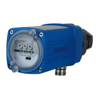
Ø120 mm, length 310 mm
(incl. purge air connection)
Ø120 mm, length 230 mm
(without purge air connection)
Permitted ambient temperature
Depends on device
see chapters 3.6.1, 3.6.2 and 3.7.6, 3.7.7
Permissible atmospheric humidity
95% relative humidity, non-condensing
Permitted operating modes:
intermittent operation, constant operation and 72 hour
operation in accordance with (→) TRD 604
1 s (2s, 3s and 5s on request)
5s not available for versions -30 and -40)
cable 12 x 0.5mm² (AWG 20) with overall screen, cable
length: see page 47
Aluminium pressure casting, ESD paint, blue
Protection rating (in accordance
with EN 60529):
F1= 0.5 A slow-blow, MST 250
F2= 0.5 A slow-blow, MST 250
Analogue output 0/4 20 mA
Normally open contact; active when flame ON
Ready for operation contact
Normally open contact; active when no fault (series
connection with flame contact as a thirdswitch-off path
possible)
Switching capacity of the relay
contacts
max: 0.5 A 24 V⎓ with spark suppression
Table 10.2: Technical data for the basic device
The flame monitor is equipped with insulation between the power supply
(24 V⎓) and the internal voltage. The current output is galvanically connected
to the internal power.

 Loading...