8 Adjusting the flame monitor
100 D−LX 200, D−LX 720
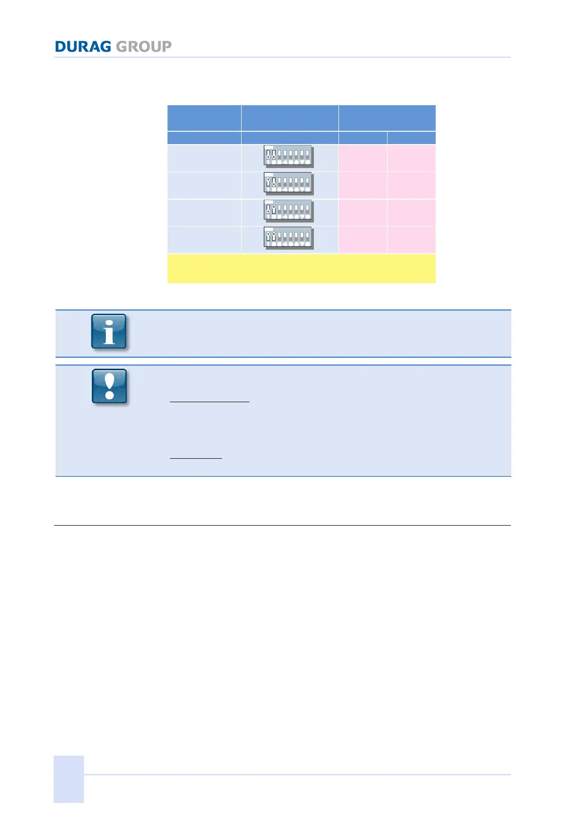
changed when adjusting the gain characteristics curve. Use the switch settings
for the safety time stated on the type label for control purposes Table 8.2.
*
the DIP positions 1 and 2 must be set to the corresponding safety
times as marked on the type label!
Table 8.2: Switch setting of the MODE switch S3 and S4 (safety time)
In order to avoid an error shutdown, set the MODE switches S3 and S4 to
the same settings within 8s!
When reconnecting the housing hood, ensure that the circuit boards feed
correctly into the guide rails and the connecting cable is not squashed.
Standard housing:
The gasket between the hood and the front part of the housing must sit fully
in the front part of the housing. Tighten the long screws for holding the hood
in place, so that the hood lies all around flush on the front part of the housing.
(max. torque: 1 Nm)
Ex-housing:
To close see chapter 7.5 on page 74ff
8.7 Modbus
This chapter concerns itself with the device-specific areas of the Modbus
interface and the Modbus implementation for the D−LX 200, D−LX 720.
Therefore this description does not present complete information about all
aspects of the Modbus protocol.
General information regarding Modbus and the DURAG Modbus can be found in
the separate DURAG Modbus manual and on-line at (http://www.modbus.org/).
The (→) RS-485/485/field bus interface of the D−LX 200, D−LX 720 is for
provision of parameters and settings, and the enquiring on the current status.
The Mobus protocol is used.
The data communication is on a master(client) / slave(server) basis. The
Compact Flame Monitor functions exclusively as a "slave", i.e. it responds or
answers to valid Modbus enquiries only at the request of the Modbus master.
The RS-485/Modbus interface permits data transmission over long distances
(up to 1200 m) and permits several devices to be connected in parallel. The
data cables must be installed as twisted pairs.
 Loading...