7 Installation, commissioning
76 D−LX 200, D−LX 720
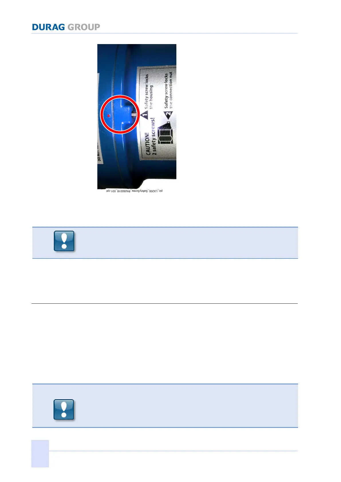
Figure 7.11: Correctly closed housing
This is then the case when the safety screw is directly next to the red point of
the Ex-middle section.
If the external thread sits correctly in the internal thread, the housing hood is
easy to unscrew. No tools are needed for this!
Under no circumstances force the thread. This can cause damage.
3. Screw the safety screw (hex socket) tight with a few clockwise turns to avoid
unwanted loosening of the housing hood.
7.6 Electrical connection
Installation is in accordance with the dimensional drawing of the Compact
Flame Monitor D−LX 200, D−LX 720 (see Figure 11.3 page 118, and
Figure 11.4 page 119). Electrical installation is done in compliance with local
regulations and the corresponding wiring diagram.
Protection rating of the flame monitor only applies with the hood in place.
Operation of the Compact Flame Monitor when open is not permissible.
The Compact Flame Monitor can bridge power failures of up to 20ms.
The position of the fuses F1 and F2 is apparent in Figure 7.12.
After changing the fuses: Check the reliability of the function of the
relay for the Flame ON message!
Fuse F2 protects the relay for the Flame ON message. Should this fuse need to
be replaced, it is imperative that the reliability of the function of this relay is
checked. Only then can continued use of the Compact Flame Monitor be allowed.
 Loading...