7 Installation, commissioning
80 D−LX 200, D−LX 720
7.6.1 Cable and screen
The Compact Flame Monitor D−LX 200, D−LX 720 is designed for switching
24 V⎓ voltages via the operation readiness contact and the flame contact. The
contacts can generate sparks when switching a load, which, in the case of
long line lengths, can affect other switching circuits.
It is advisable to install a junction box near the flame monitor and to execute
the subsequent cabling with separate, shielded lines.
Over short distances (< 5m) the lines are unsusceptible to interference and do
not need to be protected.
The single wires can be defined according to the system-specific
requirements. The cross-section for the 24 V⎓ supply line must be large
enough to ensure that R = 10 per wire is not exceeded. The D−LX 200,
D−LX 720 flame monitor will then still operate reliably at
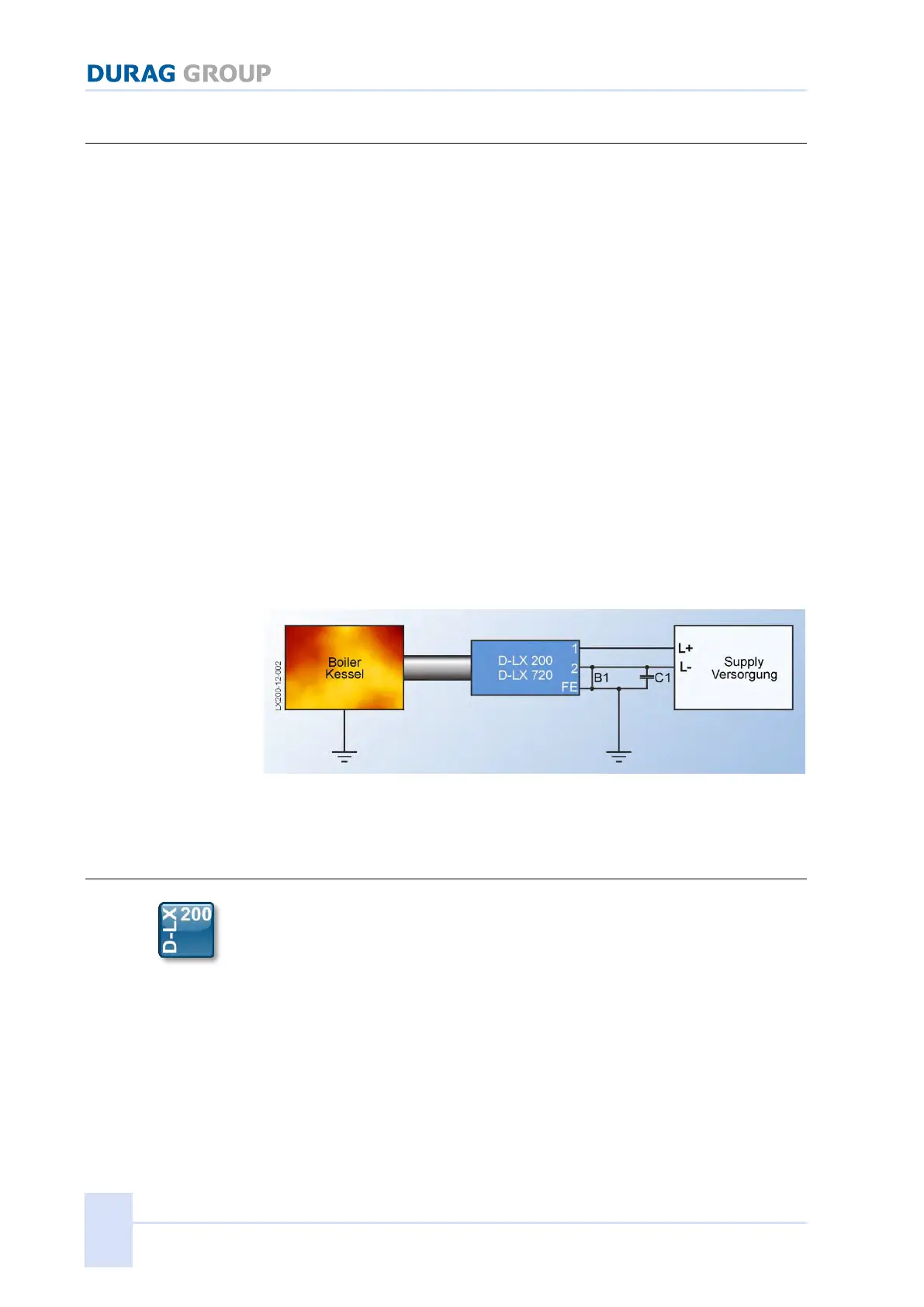
The D−LX 200, D−LX 720 has an electrically isolated design. There is no
connection between the 24 V⎓ supply voltage and the internal voltage of the
flame monitor. If faults occur after installation, the cause can be a ripple
voltage between the 0V potential of the supply and the internal operating
voltage.
This can be remedied with a capacitive coupling C1= approx. 100nF or by
eliminating the electrical isolation with a bridge B1.
Figure 7.15: Elimination of the potential separation
7.7 Installation, purge air supply
The purge air connection on the Compact Flame Monitor has the task of
keeping the sighting tube and the viewing glass clear of dirt from the
combustion chamber. This is done by maintaining a flow of air towards the
combustion chamber, which carries away even heavier particles. For
combustion systems with low particle levels such as gas-firing, an air speed of
v=1 m/s in a 1¼" sighting tube gives sufficient purging (air consumption
approx. 3m³/h). On the other hand, for combustion systems with particle levels
such as coal firing, greater purge air quantities are required (air speed
v=3 m/s) to keep them clean. The speed of the purge air in the sighting tube is
only an indicative value and must be determined specifically for each system.
A ½" internal screwed connection is provided for the purge air on the flame monitor.
The flame monitor should be checked regularly to ensure that the optics are
clean and securely seated in the front part.
If flame monitors must be mounted to sighting tubes with high temperature
exposure, the purge air also serves as coolant. In such cases it is
 Loading...