E 11 53
8 Limit switch
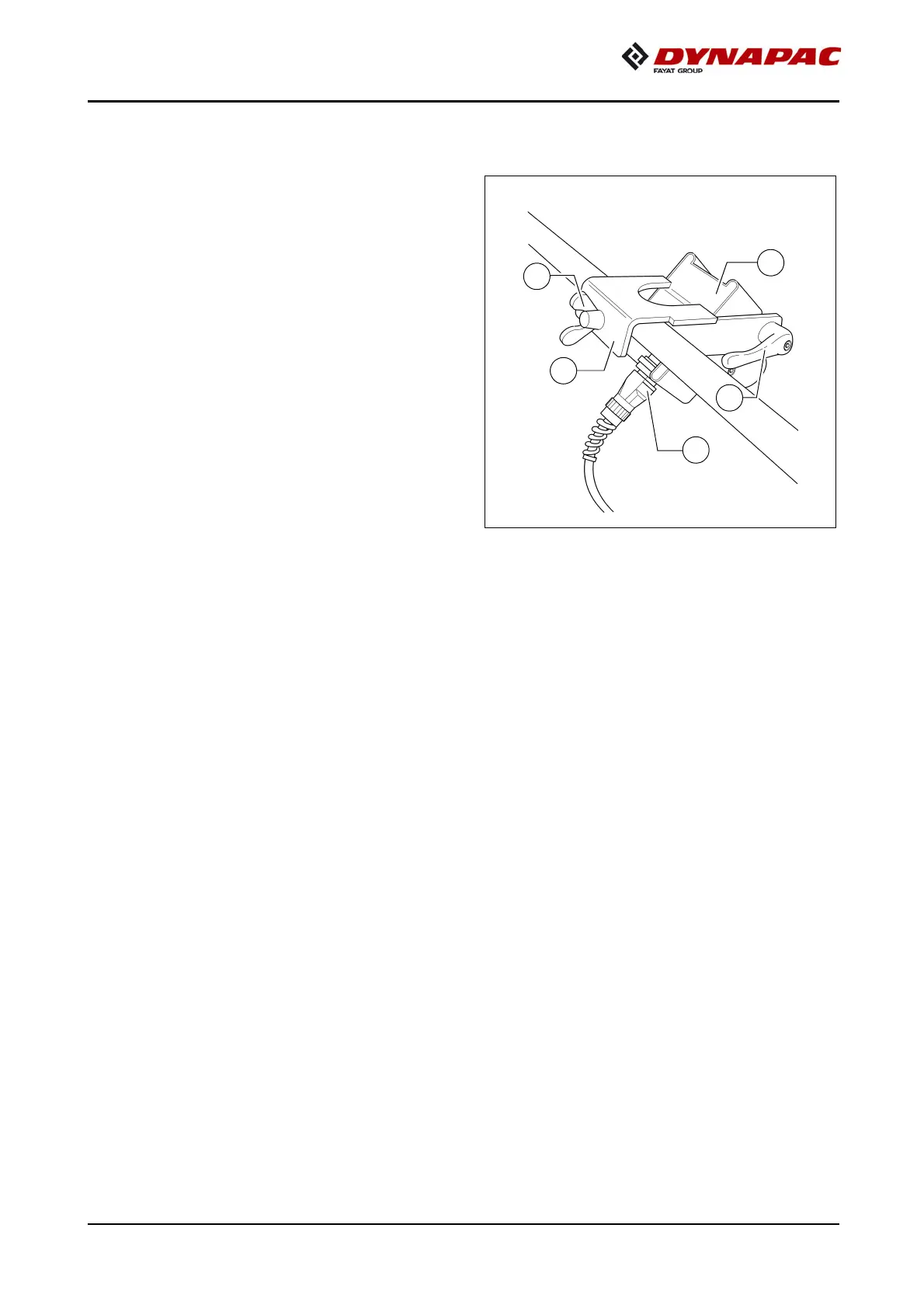
8.1 Auger limit switches
(left and right) -
mounting the PLC version
The auger's ultrasonic limit switch is
mounted on both sides on the side
board's handrail.
- Place the sensor bracket (1) onto the
handrail, align it and tighten with a
wing bolt (2).
- Align the sensor (3) and secure with a
clamping lever (4).
- Connect the left or right sensor's con-
nection cable (5) to the intended re-
mote control bracket sockets.
A
The connection cables are connected to the relevant sockets on the remote control
bracket.
A
The sensors should be adjusted so that 2/3 of the augers are covered with the paving
material.
A
The paving material must be conveyed over the full working width.
A
We recommend adjusting the limit switch positions during material distribution.