Home
Dynapac
Construction Equipment
SD2550C
Page 375 (Seals and sealing rings (5))
Dynapac SD2550C - Seals and sealing rings (5)
468 pages
Manual
Save Page as PDF
To Next Page
To Next Page
To Previous Page
To Previous Page
Loading...
F 40 9
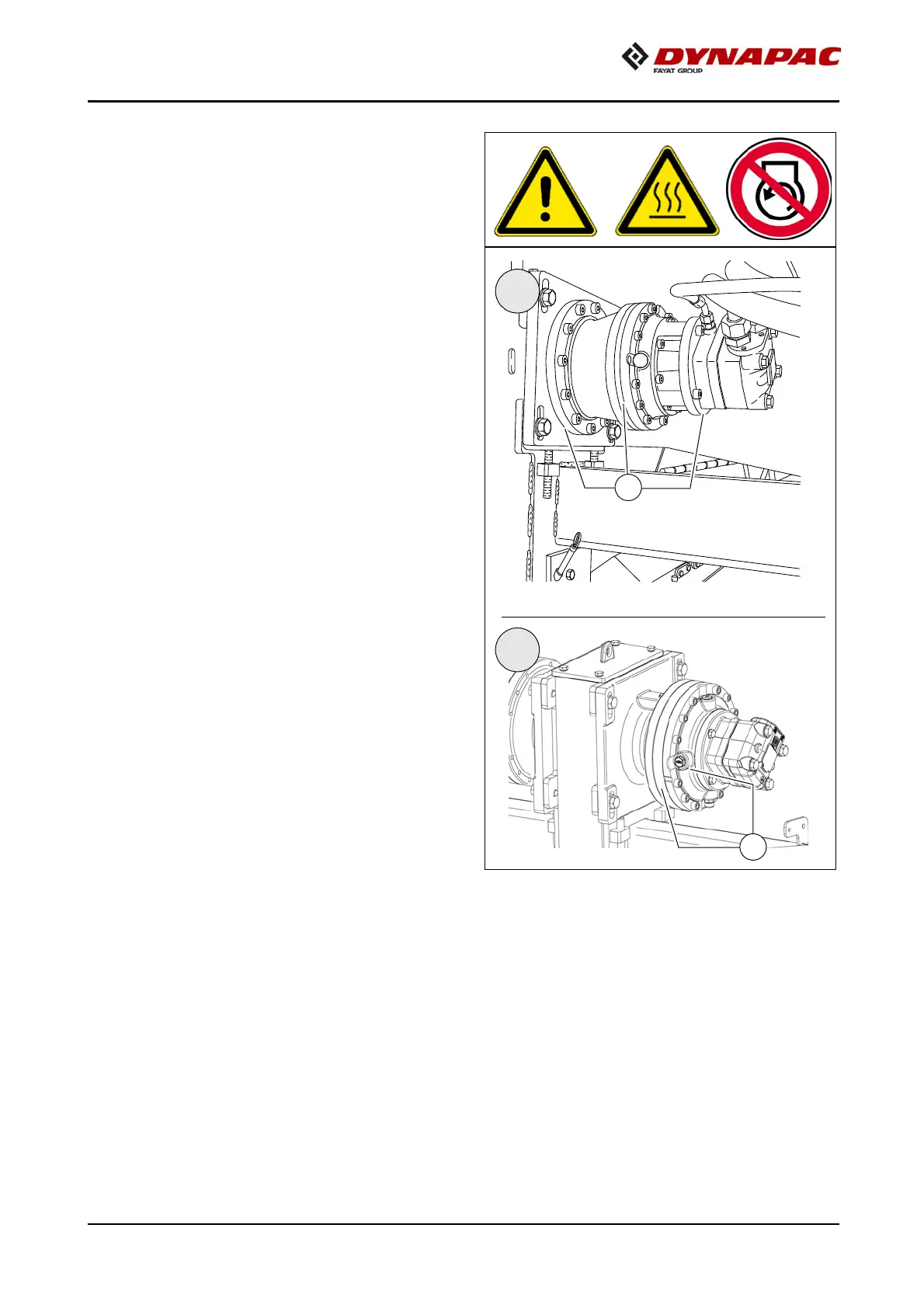
Seals and sealing rings (5)
A
After reaching operating temperature,
check the gearbox for leaks.
m
In case of visible leaks, e.g. between the
flange surfaces (A)
of the gearbox, re-
placement of the s
eals and se
aling rings
is necessary.
I
II
A
A
374
376
Table of Contents
Main Page
Table of contents
3
V Preface
13
1 General safety instructions
14
1.1 Laws, guidelines, accident prevention regulations
14
1.2 Safety signs, signal words
15
"Danger"!
15
"Warning" !
15
"Caution" !
15
"Note" !
15
1.3 Other supplementary information
15
1.4 Warnings
16
1.5 Prohibitive symbols
18
1.6 Protective equipment
19
1.7 Environmental protection
20
1.8 Fire prevention
20
1.9 Additional information
21
2 CE identification and Declaration of Conformity
22
3 Guarantee conditions
22
4 Residual risks
23
5 Sensibly predictable incorrect usage
24
A Correct use and application
25
B Vehicle description
27
1 Application
27
2 Description of assemblies and functions
28
2.1 Vehicle
29
Construction
29
3 Danger zones
33
4 Safety devices
34
5 Technical data, standard configuration
36
5.1 Dimensions (all dimensions in mm)
36
5.2 Allowed angle of rise and slope
37
5.3 Permissible approach angle
37
5.4 Weights SD2550C (all weights in t)
38
5.5 Weights SD2550CS (all weights in t)
38
5.6 Performance data SD2550C
39
5.7 Performance data SD2550CS
40
5.8 Travel drive/traction unit
41
5.9 Engine SD2550C
41
5.10 Engine SD2550CS
41
5.11 Hydraulic system
41
5.12 Material compartment (hopper)
42
5.13 Material transfer
42
5.14 Material distribution SD2550C
42
5.15 Material distribution SD2550CS
42
5.16 Screed lifting device
43
5.17 Electrical system
43
5.18 Permissible temperature ranges
43
6 Location of instruction labels and identification plates
44
6.1 Warning signs
47
6.2 Information signs
50
6.3 CE marking
52
6.4 Instructive symbols, prohibitive symbols, warning symbols
53
6.5 Danger symbols
54
6.6 Further warnings and operating instructions
55
6.7 Identification label for the paver finisher (41)
57
7 EN standards
58
7.1 Continuous sound pressure SD2550C, Cummins QSB 6.7-C260
58
7.2 Operating conditions during measurement
58
7.3 Measuring point configuration
58
7.4 Continuous sound pressure SD2550CS, Cummins QSB 6.7-C260
59
7.5 Operating conditions during measurement
59
7.6 Measuring point configuration
59
7.7 Vibration acting on the entire body
60
7.8 Vibrations acting on hands and arms
60
7.9 Electromagnetic compatibility (EMC)
60
C 11 Transportation
61
1 Safety regulations for transportation
61
2 Transportation on low-bed trailers
62
2.1 Preparations
62
3 Securing the load
64
3.1 Prepare the low-bed trailer
64
3.2 Driving onto the low-bed trailer
65
3.3 Lashing equipment
66
3.4 Loading
67
3.5 Preparing the machine
68
4 Securing the load
69
4.1 Securing at the sides
69
4.2 Securing at the front
69
4.3 Securing at the rear - screed with side board
70
4.4 Securing at the rear - screed without side board
71
Step 1: fasten lashing straps
71
Step 2: fasten lashing chains
71
5 Control panel transport safeguard:
72
5.1 After transportation
73
Protective roof (o)
74
6 Transportation
76
6.1 Preparations
76
6.2 Driving mode
78
7 Loading by crane
79
8 Towing
82
9 Safely parking the vehicle
84
9.1 Lifting the vehicle with hydraulic lifts, lifting points
85
D 11 Operation
87
1 Safety regulations
87
2 Controls
89
2.1 Operating panel
89
2.2 Special functions
136
Reversible conveyor
136
3 Remote control
139
D 21 Operation
157
1 Operation of the input and display terminal
157
Button layout on the display
157
Command symbols
158
1.1 Menu operation
159
Main menu
161
Displays:
161
Active / inactive display function
165
"Engine speed" menu
166
Set-up menu Engine speed
166
Measured value display Drive engine
167
"Paving parameters" menu
168
Set-up menu Paving parameters
168
Paving parameters Save
169
Paving parameters Load
169
Actual value display Auger, conveyor, tamper, vibration(o)
170
Set-up menu Screed heater
170
Menu Paving area / automatic steering unit
171
Menu "Machine settings memory"
172
Set-up menu - "Delayed screed start"
172
Menu "Camera display"
173
"Camera 2" display
173
Menu "Front wheel drive" (o)
174
Menu - "Error memory"
175
Display "Machine error messages"
175
Display "Engine error messages"
176
Menu "System information & basic settings"
177
Menu "Service"
178
Set-up menu "Levelling"
179
Set-up menu "Screed type"
179
Set-up menu "Terminal settings"
180
System menu - "Basic settings" display
180
2 Terminal error messages
181
2.1 Drive engine error codes
182
2.2 Error codes
184
3 Menu structure of the setting and display menus
191
D 30 Operation
193
1 Operating elements on the paver finisher
193
1.1 Control elements on the operator's control station
193
Protective roof (o)
194
Ladder
196
Storage space
196
Control platform, moveable (o)
197
Control platform lock (o)
198
Operating panel
199
Protective cabin (o)
200
Windscreen wiper
201
.Emergency actuation control platform, movable
202
Seat console
203
Driver's seat, type I
204
Driver's seat, type II
205
Fuse box
206
Batteries
207
Main battery switch
207
Hopper transport safeguard
208
Screed lock, mechanical (o)
208
Screed lock, hydraulic (o)
209
Paving thickness indicator
210
Auger lighting (o)
211
Engine compartment lighting (o)
211
LED working light (o)
212
500 watt spotlight (o)
213
Camera (o)
213
Auger height adjustment ratchet (o)
214
Auger height indicators
214
Sensor rod / sensor rod extension
215
Manual separator fluid spray (o)
217
Separator fluid spraying system (o)
218
Conveyor limit switches - PLC version
219
Conveyor limit switches - conventional version
220
Ultrasonic auger limit switches (left and right) - PLC version
221
Ultrasonic auger limit switches (left and right) - conventional version
222
24 volt / 12 volt sockets (o)
223
Pressure control valve for screed charging/relieving
224
Pressure control valve for paving stop with relieving
224
Manometer for screed charging/relieving
224
Central lubrication system (o)
225
Lane clearer (o)
226
Screed eccentric adjustment
227
Push roller crossbar, adjustable
228
Push roller crossbar, hydraulically extendable (o)
229
Push roller damping, hydraulic (o)
229
Fire extinguisher (o)
230
First-aid kit (o)
230
Rotary beacon (o)
231
Fuelling pump (o)
232
Illuminated balloon (o)
233
Installation and operation
234
Maintenance
235
Replacing the lamp
235
D 41 Operation
237
1 Preparing for operation
237
Required devices and aids
237
Before starting work (in the morning or when starting paving)
239
Check list for the vehicle operator
239
1.1 Starting the paver finisher
242
Before starting the paver finisher
242
"Normal" starting
242
External starting (starting aid)
244
After starting
247
Observe indicator lamps
249
Engine coolant temperature check (79)
249
Battery charge indicator (83)
249
Oil pressure indicator lamp for the diesel engine (86)
249
Oil pressure indicator lamp for the travel drive (87)
251
1.2 Preparation for transportation
253
Driving and stopping the paver finisher
255
1.3 Preparations for paving
256
Separator fluid
256
Screed heater system
256
Direction marks
257
Loading/conveying material
259
1.4 Starting for paving
261
1.5 Checks during paving
262
Paver function
262
Quality of the layer
262
1.6 Paving with "screed control at paving stop" and "screed charging/relieving"
263
General
263
Screed charging/relieving
265
Screed control with paver finisher stop / in paving operation (screed stop / paving stop / floating paving)
265
Adjusting the pressure
269
Setting pressure for screed control with paving stop + relieving:
269
1.7 Interrupting/terminating operation
271
During breaks (e.g. the material supply truck is late)
271
During longer breaks(e.g. lunch break)
271
When work is finished
273
2 Malfunctions
274
2.1 Problems during paving
274
2.2 Malfunctions on the paver finisher or screed
276
E 11 Set-up and modification
279
1 Special notes on safety
279
2 Distribution auger
280
2.1 Height adjustment
280
Grain sizes up to 16 mm
280
Grain sizes > 16 mm
280
2.2 Mechanical adjustment with ratchet (o)
281
2.3 Hydraulic adjustment (o)
281
2.4 Height adjustment for large working widths / with brace
282
3 Auger extension
284
3.1 Mounting extension parts
285
Mounting the material shaft and auger extension
285
Mounting the outer auger bearing
286
Mounting the auger end bearing
287
3.2 Auger extension chart
288
Auger upgrading, working width 3.14 m
290
Auger upgrading, working width 3.78 m
290
Auger upgrading, working width 4.42 m
290
Auger upgrading, working width 5.06 m
291
Auger upgrading, working width 5.70 m
291
Auger upgrading, working width 6.34 m
292
Auger upgrading, working width 6.98 m
293
Auger upgrading, working width 7.62 m
294
Auger upgrading, working width 8.26 m
295
Auger upgrading, working width 8.90 m
296
Auger upgrading, working width 9.54 m
297
Auger upgrading, working width 10.18 m
298
Auger upgrading, working width 10.82 m
299
Auger upgrading, working width 11.46 m
300
Auger upgrading, working width 12.10 m
301
Auger upgrading, working width 12.74 m
302
3.3 Mounting the auger brace
303
3.4 Aligning the auger
305
3.5 Material shaft, hinged
307
3.6 Hopper scraper
308
3.7 Crossbeam guide
309
4 Offsetting the screed
310
5 Levelling
311
5.1 Slope controller
311
5.2 Mounting the sensor arm
312
5.3 Mounting the grade control system
312
5.4 Setting up the sensor arm
313
5.5 Big ski 9 m, big ski 13 m
314
Mounting the big ski bracket on the crossbeam
316
Mounting the swivel arms
317
Mounting the centre element
318
Extending the big ski
319
Mounting the sensor bracket
320
Mounting and aligning the sensors
321
Mounting the distributor box
322
Connection diagram
323
5.6 Levelling shoe 6m, 9m
324
6 Automatic steering unit
326
6.1 Mounting the automatic steering unit on the paver finisher
327
Mounting and aligning the sensor
328
Connecting the sensor
328
Automatic steering unit operating instructions
329
7 Emergency stop during feeder operation
330
8 Limit switch
331
8.1 Auger limit switches (left and right) - mounting the PLC version
331
9 Special accessories
332
9.1 Material bucket
332
Application
332
Description of assemblies and functions
333
Technical data
334
Dimensions, bucket MH2500 - (short version)
334
Dimensions, bucket MH2550 - (long version)
335
Weights
336
Volume
336
10 Identification points
337
10.1 Information signs
338
10.2 Warning signs
338
10.3 Further warnings and operating instructions
338
10.4 Instructive symbols, prohibitive symbols, warning symbols
339
Load securing - bucket
340
Prepare the low loader
340
Lashing equipment
341
Lashing
342
Loading with the crane - MH2500
344
Loading with the crane - MH2550
345
Lash the bucket in the paver
347
Operation
349
Operation with a feeder with slewing belt
350
Preparations for paving
350
Separator fluid
350
Cleaning the bucket
351
11 Screed
352
12 Electrical connections
352
12.1 Machine operation without remote control / side board
353
F 10 Maintenance
355
1 Notes regarding safety
355
F 26 Maintenance review
357
1 Maintenance review
357
F 31 Maintenance - conveyor
359
1 Maintenance - conveyor
359
1.1 Maintenance intervals
361
1.2 Points of maintenance
362
Chain tension, conveyor (1)
362
Conveyor drive - drive chains (2)
364
Conveyor deflectors / conveyor plates (3)
365
F 40 Maintenance - auger assembly
367
1 Maintenance - auger assembly
367
1.1 Maintenance intervals
369
1.2 Points of maintenance
371
Outer auger bearing (1)
371
Auger planetary gear (2)
372
Drive chains of the augers (3)
373
Auger box (4)
374
Seals and sealing rings (5)
375
Gearbox bolts Check tightening (6)
376
Mounting screws - Outer auger bearing Check tightening (7)
377
Auger blade (8)
378
F 52 Maintenance - engine assembly Tier 4i (o)
379
1 Maintenance - engine assembly
379
1.1 Maintenance intervals
381
1.2 Points of maintenance
384
Engine fuel tank (1)
384
Engine lube oil system (2)
385
Engine fuel system (3)
388
Engine air filter (4)
390
Engine cooling system (5)
392
Engine drive belt (6)
394
Crankshaft ventilation filter (7)
395
Exhaust system - particulate filter (8)
396
F 60 Maintenance - hydraulic system
397
1 Maintenance - hydraulic system
397
1.1 Maintenance intervals
399
1.2 Points of maintenance
401
Hydraulic oil tank (1)
401
Suction/return flow hydraulic filter (2)
403
Bleeding the filter
404
Ventilation filter
404
High-pressure filter (3)
405
Pump distribution gear (4)
406
Bleeder
407
Hydraulic hoses (5)
408
Marking hydraulic hoses / storage period, period of use
410
Auxiliary flow filter (6)
411
F 74 Maintenance – drive units
413
1 Maintenance – drive units
413
1.1 Maintenance intervals
415
1.2 Points of maintenance
418
Chain tension (1)
418
Bottom plates (2)
421
Rollers (3)
422
Planetary gear (4)
423
Screw connections
425
F 81 Maintenance - electrical system
427
1 Maintenance - electrical system
427
1.1 Maintenance intervals
429
1.2 Points of maintenance
430
Batteries (1)
430
Recharging the batteries
431
Alternator (2)
432
Insulation faults
433
Cleaning the generator
434
Electrical fuses / relays (3)
435
Fuses in terminal box (B)
436
Relays in terminal box (C)
438
Relays in the engine compartment (E)
440
F 90 Maintenance - lubricating points
441
1 Maintenance - lubricating points
441
1.1 Maintenance intervals
442
1.2 Points of maintenance
443
Central lubrication system (1)
443
Bearing points (2)
447
F 100 Tests, stopping ...
449
1 Tests, checks, cleaning, stopping
449
1.1 Maintenance intervals
450
2 General visual inspection
451
3 Check that the bolts and nuts fit firmly
451
4 Inspection by an expert
452
5 Cleaning
453
5.1 Cleaning the hopper
454
5.2 Cleaning the conveyor and auger
454
6 Preserving the paver finisher
455
6.1 Shutdowns for up to 6 months
455
6.2 Shutdowns lasting from 6 months to 1 year
455
6.3 Recommissioning the machine
455
7 Environmental protection, disposal
456
7.1 Environmental protection
456
7.2 Disposal
456
8 Bolts - torques
457
8.1 Standard metric threads - strength class 8.8 / 10.9 / 12.9
457
8.2 Fine metric threads - strength class 8.8 / 10.9 / 12.9
458
F 112 Lubricants and operating substances
459
1 Lubricants and operating substances
459
1.1 Capacities
461
2 Operating substance specifications
462
2.1 Drive engine - fuel
462
2.2 Drive engine - Lube oil
462
2.3 Cooling system
462
2.4 Hydraulic system
463
2.5 Pump distribution gear
463
2.6 Drive unit planetary gear
463
2.7 Auger drive planetary gear
463
2.8 Auger box
464
2.9 Grease
464
2.10 Hydraulic oil
465
Related product manuals
Dynapac SD2500C
480 pages
Dynapac SD2500W
452 pages
Dynapac Svedala Demag DF 115 P/D
234 pages
Dynapac LH700
25 pages
Dynapac CA 602
30 pages
Dynapac CA 301
32 pages
Dynapac CC1300
100 pages
Dynapac CA150D
32 pages
Dynapac CA 250
28 pages
Dynapac CC1200
100 pages
Dynapac CC1300C
128 pages
Dynapac CA 262 Series
40 pages