Eagle Access Control Systems, Inc. www.EagleOperators.com
7
Important
Note: The following are exam-
ple applications. Your appli-
cation may vary.
It is the installer’s responsibil-
ity to choose the most suit-
able dimensions based on
site-specific issues.
Use “A Compact” dimension
only when necessary.
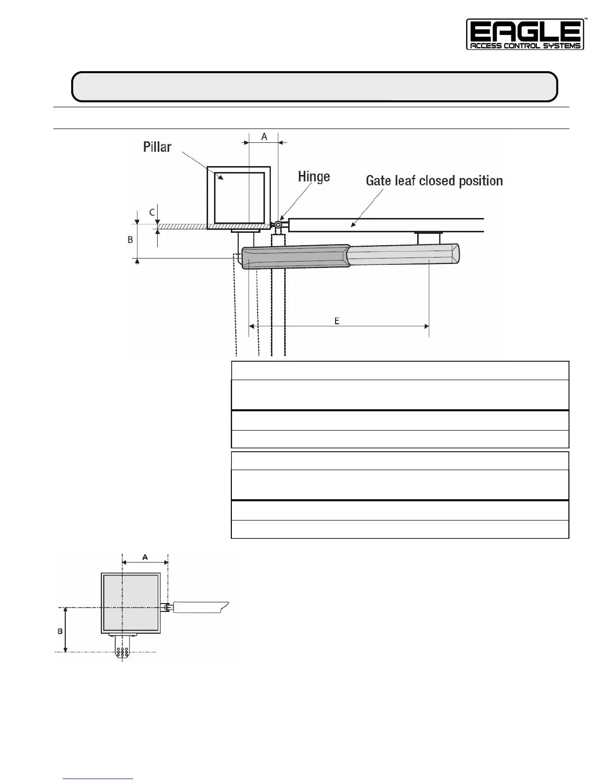
MEASUREMENTS FOR MOUNTING
INSTALLATION
Note: When attaching the Anchoring Plate & Back Bracket,
make sure the A and B measurements are correct between
the hinge axis and central bore hole on the Back Bracket.
The Back Bracket has several holes for changing the open-
ing angle of the gate.
• Increasing the B measurement decreases the opening angle resulting in slower peripheral
speed and greater motor thrust on the gate leaf.
• Increasing measurement A increases the opening angle resulting in greater peripheral
speed and reduced motor thrust on the gate leaf.
Opening
A
B
C
(MAX)
E
90° 7-3/4” 7-3/4” 4-3/4” 36-7/32”
120° 7-3/4” 5-1/2” 2-3/4” 36-7/32”
A
(Compact)
5”
5”
Opening
A
B
C
(MAX)
E
90° 5” 5” 2-1/4” 28-11/32”
120° 5” 4-1/4” 2” 28-11/32”
A
(Compact)
4-1/2”
4-1/2”
EAGLE-E7 — GATE LEAF TO 16’
EAGLE-E7 SHORT — GATE LEAF TO 10’