UPS System Installation
4-2 Eaton 93PM UPS (20–50 kW, 480V Four Wire – 50 kW Frame) Installation and Operation Manual P-164000540—Rev 4 www.eaton.com/powerquality
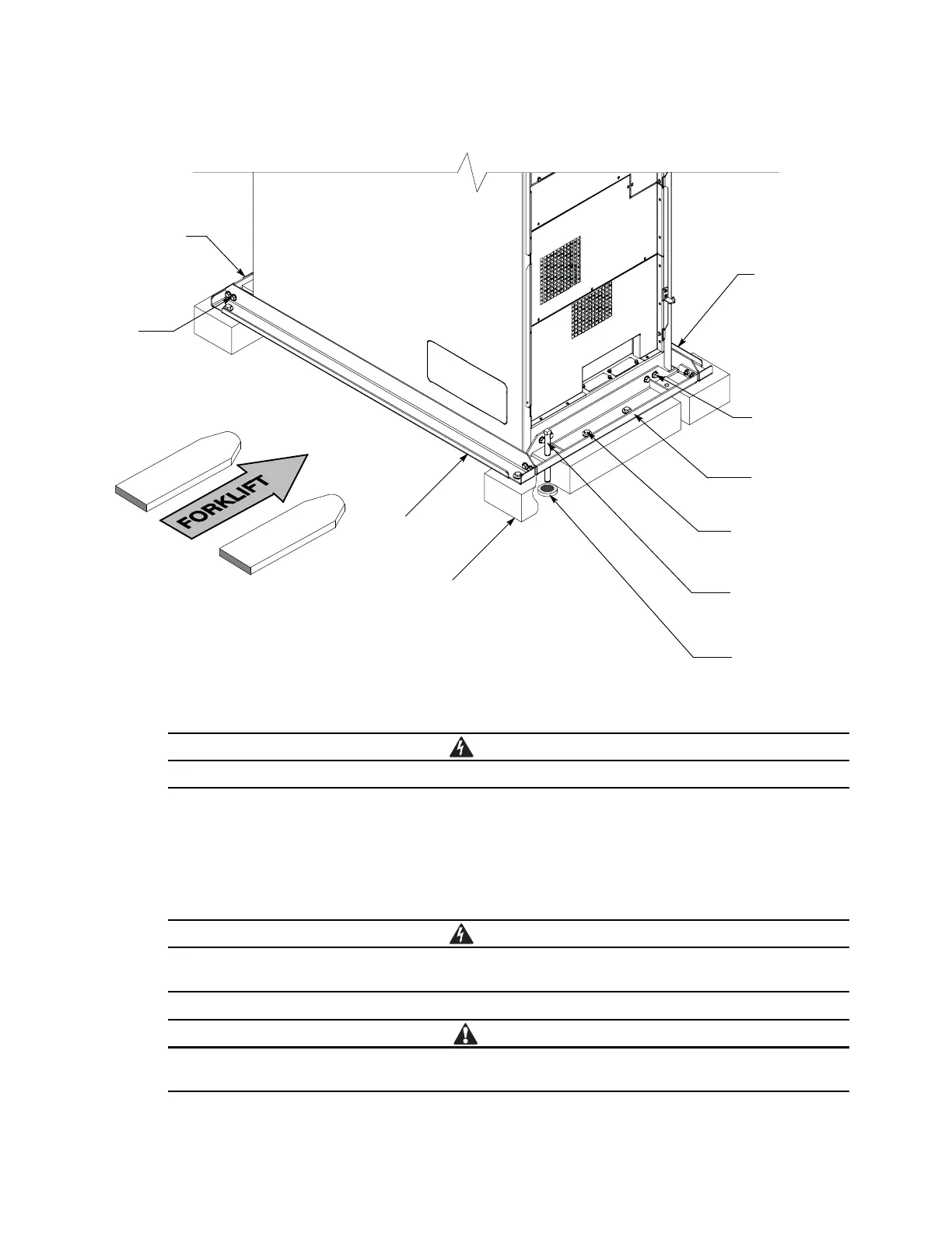
Figure 4-1. Removing the Pallet Skids and Supports – Eaton 93PM UPS
Do not remove or loosen the cabinet mounting or cabinet support bolts until instructed.
4. Loosen, but do not remove, the skid mounting bolts holding the pallet skids to the front and rear supports,
and to the left and right side supports (see Figure 4-1).
5. If a sidecar is attached to the UPS, loosen, but do not remove, the sidecar skid mounting bolts holding the
sidecar pallet skids to the sidecar front and rear supports, and to the left and right supports (see Figure 4-1
and Figure 4-2).
RISK OF INSTABILITY. Turning the jacking bolts unevenly may cause the cabinet to become
unbalanced. To prevent tipping the cabinet, raise and lower the jacking bolts evenly.
CABINET MAY TIP. Raise the UPS no more than 3 mm (1/8") above the floor (just enough to allow
the removal of the pallet skids).
Cabinet
Mounting Bolts
(4 places front)
(4 places rear)
Pallet Skid
Skid Mounting Bolts
(4 places front)
(4 places rear)
Floor Protectors
(2 places front)
(2 places rear)
Right Side
Cabinet Support
Rear Cabinet
Support
Jacking Bolts
(2 places front)
(2 places rear)
Front Cabinet
Support
Cabinet
Support Bolts
(2 places at
each corner)
Left Side
Cabinet Support
 Loading...


