UPS System Installation
4-22 Eaton 93PM UPS (20–50 kW, 480V Four Wire – 50 kW Frame) Installation and Operation Manual P-164000540—Rev 4 www.eaton.com/powerquality
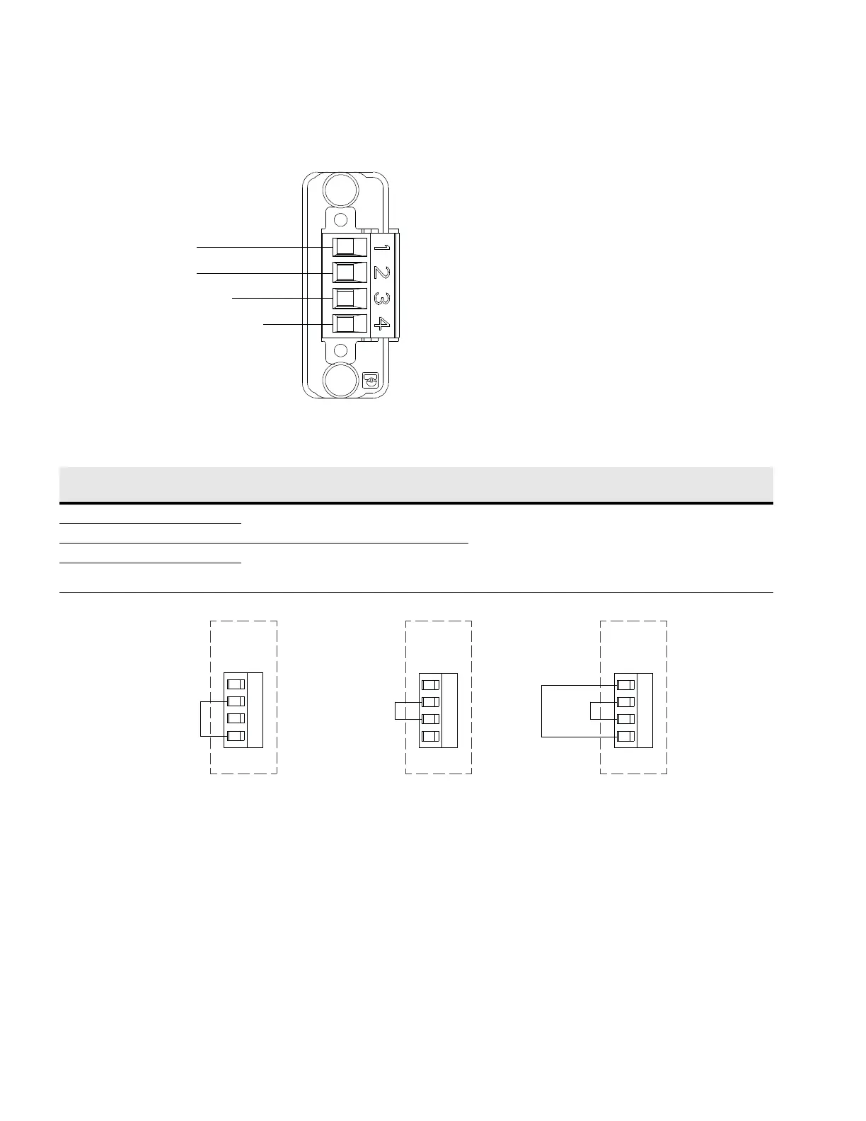
Figure 4-19. Thermal Sensor Terminal Assignments
Figure 4-20. Thermal Sensor Jumper Assignments
Thermal Sensor
Thermal Sensor Return
Jumper
Jumper
Thermal Sensor
TB11
Table 4-4. Thermal Sensor Connections and Wire Terminations
Terminal Name Description
Recommended
Minimum Wire Size
Size of Pressure
Termination
Tightening Torque
1 Jumper
Used to select battery configuration
Twisted Pair Wires
#18 AWG Use wire
rated for 600V and
Class 1 wiring
methods.
#12-#22 AWG
5–7 lb in
(0.56–0.79 Nm)
2 Jumper
3 Thermal Sensor Input: Used to signal a battery temperature out of
specification and to turn off the battery charger to
prevent thermal runaway.
4 Thermal Sensor Return
1
2
3
4
UPS
Thermal
Sensor
TB11
Jumper
Internal
Batteries
1
2
3
4
UPS
Thermal
Sensor
TB11
1
2
3
4
UPS
Thermal
Sensor
TB11
Internal and
External
Batteries
External
Batteries
Jumper
Jumper Jumper
 Loading...


