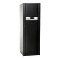
UPS Installation Plan and Unpacking
3-8 Eaton 9E UPS (40–60 kVA, 208/220V) Installation and Operation Manual P-164000058—Rev 4 www.eaton.com/powerquality
The power wiring terminals are pressure terminations, UL and CSA rated at 90°C. See Table 3-5 for external
power cable terminations.
Figure 4-7 and Figure 4-8 show the location of the UPS power cable terminals.
Table 3-5. UPS External Power Cable Terminations for the Eaton 9E-40, 9E–60/40, and 9E–60/60
Terminal Function Terminal Function
Number and Size of Pressure
Termination
AWG or kcmil
Tightening Torque
Nm (lb in)
Screw Size and Type
AC Input to UPS Rectifier L1 Phase A 1 – #6-250 22.6 (200) 1/4 in. Hex
L2 Phase B 1 – #6-250 22.6 (200) 1/4 in. Hex
L3 Phase C 1 – #6-250 22.6 (200) 1/4 in. Hex
N Neutral 2 – #6-250 22.6 (200) 1/4 in. Hex
AC Input to Bypass L1 Phase A 1 – #6-250 22.6 (200) 1/4 in. Hex
L2 Phase B 1 – #6-250 22.6 (200) 1/4 in. Hex
L3 Phase C 1 – #6-250 22.6 (200) 1/4 in. Hex
N Neutral 2 – #6-250 22.6 (200) 1/4 in. Hex
AC Output to Critical Load L1 Phase A 1 – #6-250 22.6 (200) 1/4 in. Hex
L2 Phase B 1 – #6-250 22.6 (200) 1/4 in. Hex
L3 Phase C 1 – #6-250 22.6 (200) 1/4 in. Hex
N Neutral 2 – #6-250 22.6 (200) 1/4 in. Hex
DC Input from External Battery + Battery (+) 2 – #6-250 22.6 (200) 1/4 in. Hex
– Battery (-) 2 – #6-250 22.6 (200) 1/4 in. Hex
Customer Ground Ground Ground 4 – #6-300 31.1 (275) 5/16 in. Hex
NOTE Customer ground, sized in accordance with NEC Table 250.122, can be run in any conduit listed in Table 3-6.

 Loading...