UPS System Installation
Eaton 9E UPS (40–60 kVA, 208/220V) Installation and Operation Manual P-164000058—Rev 4 www.eaton.com/powerquality 4-7
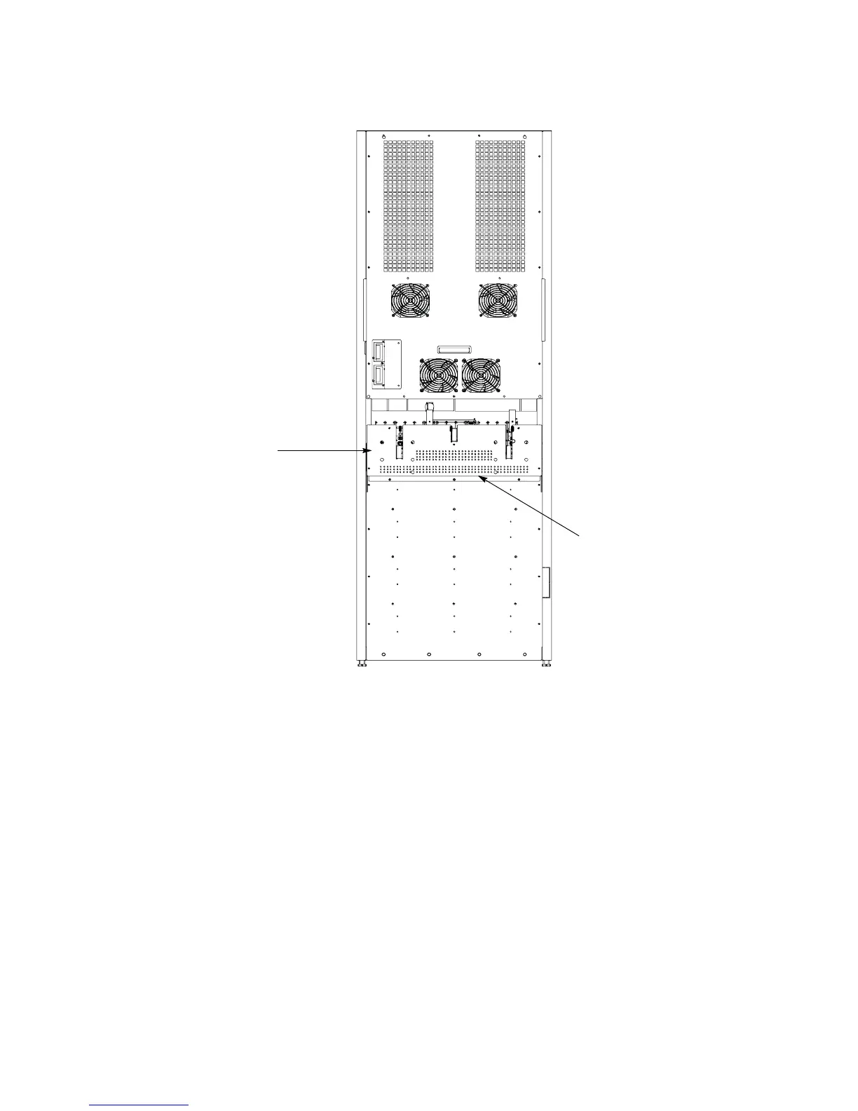
Figure 4-6. UPS Power Terminal Cover Base Installation and Conduit Landing Wire Entry Locations
4.4 External Battery Cabinet Installation
If installing External Battery Cabinets (EBCs), refer to the Eaton 9E External Battery Cabinet Installation Manual
listed in paragraph 1.8 for installation instructions.
After the EBC is installed, proceed to paragraph 4.5 if installing an Integrated Transformer Cabinet (ITC), to
paragraph 4.6 if installing an Integrated Accessory Cabinet-Bypass (IAC-B), to paragraph 4.7 if installing a
Integrated Accessory Cabinet-Tie (IAC-T), to paragraph 4.8 if installing a Integrated Accessory Cabinet-Tie and
Bypass (IAC-TB), or to paragraph 4.9 if installing an Integrated Accessory Cabinet-Distribution (IAC-D);
otherwise, proceed to paragraph 4.10 to complete the wiring of the UPS.
4.5 Integrated Transformer Cabinet Installation
If installing an Integrated Transformer Cabinet (ITC), refer to the Eaton 9E Integrated Transformer Cabinet
Installation Manual listed in paragraph 1.8 for installation instructions.
After the ITC is installed, proceed to paragraph 4.6 if installing an IAC-B, or to paragraph 4.9 if installing an IAC-D;
otherwise, proceed to paragraph 4.10 to complete the wiring of the UPS.
Conduit Landing for AC Input, Output,
and Bypass, DC Input, and REPO.
(Install conduit to bottom of plate.)
Power Terminal Cover
Base Installed
Back