1.8. 33-790-11
Page 9
Section 3 - Preliminary Examination
of
Circuit Breaker
3.0 GENERAL
Read these instructions carefully and look at the breaker
as it stands out
of
the compartment before trying to oper-
ate
it.
Refer to Figures
5,
6,
7 and
8.
The complete drawout element includes the circuit
breaker itself and its auxiliaries. The circuit breaker con-
sists
of
four major components:
1.
The operating mechanism.
2.
The contacts, operated
by
the mechanism.
3.
The arc chutes, which interrupt the arc which always
results from opening the breaker under load or short
circuit conditions.
4.
The Amptector® solid-state overcurrent tripping sys-
tem.
ORAWOOT
Ullt!T
PmltTIOl\I
ll\lf>Jc.ATO~·--
S?lUNca
Cffi\itQE----
tNDt<:ATOR
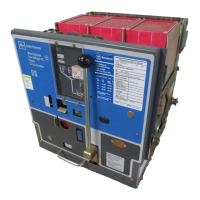
Fig. 5 View Showing Controls on the Panel (391066)
Effective October 1998
The remainder
of
the drawout element includes the fol-
lowing auxiliary components:
1.
lnterphase insulating barriers which isolate the arc
chutes from each other and from ground.
2.
Drawout element frame and rollers.
3.
The levering device, for placing the element into its
various positions inside the compartment.
4.
The main disconnecting contacts, for connecting the
breaker to power source and load.
5.
The secondary contacts, for connecting the control
circuits to the electrical operating parts
of
the ele-
ment.
6.
The interlocks, which increase the safety
of
opera-
tion.
7.
Drawout element position indicator.
EMERGlKl\ICV
------1DHAm:nNG
HANDLE
Courtesy of NationalSwitchgear.com

 Loading...


