1.8. 33-790-11
Fig.
72
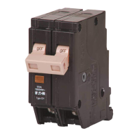
Latch Check Switch (392298)
Since this is a solid-state device, no maintenance will be
required; and the same cautions apply as previously
stated for the Amptector trip unit. Warranty will be void if
there is any evidence
of
tampering.
8.7.4 Latch Check Switch
The Latch Check Switch consists
of
a switch mounted on
the inside at the left hand side sheet
of
the circuit
breaker. The switch is located so that when the breaker
AND
LEVER
Fig.
74
Auxiliary Switch Construction Details (PRE-1989)
Effective October 1998
Page 65
trip shaft is
in
the "reset" position a normally closed con-
tact
of
the switch is closed. See Figures 72 and 73. When
this switch is supplied, the contact is usually connected
in
the closing circuit
of
the circuit breaker to insure that the
tripping system is reset before the circuit can be ener-
gized to close the breaker.
TRIP
ACTUATOR
Fig.
73
Latch Check Switch Operation
8.7.5 Auxiliary Switches
c
As shown
in
Figure 65, there may be from one to three
auxiliary switches located to the right
of
the Amptector
trip unit. Each switch has four contacts, which may be
either normally open
or
normally closed. See Figure 74
for construction. Auxiliary switch contacts are rated 10
amperes at 120/240 volts AC, 10 amperes at 125 volts
DC, and 2 amperes at 250 volts DC.
CONTACT
ROTOR
CASE
Ii--
I I
--44L~-b'>h'--++---+-
'
CONTACT
FINGER
Courtesy of NationalSwitchgear.com
 Loading...