3 Inbetriebnahme
3.2 Zuordnung zwischen Status-LEDs und eingestelltem Nennstrom
Elektronischer Motorstarter EMS/EMS Electronic Motor Starter 04/15 MN03407009Z-DE/EN www.eaton.com 19
3.2 Zuordnung zwischen Status-LEDs und eingestelltem Nennstrom
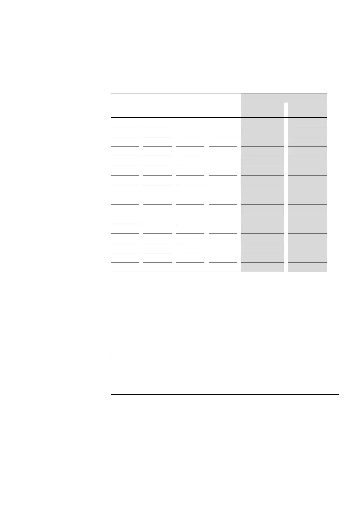
Tabelle 6: Status-LEDs und eingestellter Nennstrom
3.3 Motor mit Bremse
Wird ein Motor mit Bremse (Anschluss am Motorklemmbrett) angeschlos-
sen, muss die 400-V-AC-Bremse an den Anschlüssen 2/T1 und 6/T3 ange-
bunden werden. Eine 230-V-AC-Bremse ist am Anschluss 4/T2 und dem
Sternpunkt des Motors anzuschließen.
Die Ansteuerung von externen Bremsen erfolgt über separate Hilfsschütze
(z. B. DILA).
LED-Code Nennstrom [mA]
PWR R/ON L/- ERR EMS-…-2,4-… EMS-…-9-…
0 0 0 0 180 1500
0 0 0 1 250 2000
0
0 1 0 410 2500
0 0 1 1 560 3000
0 1 0 0 710 3500
0
1 0 1 870 4000
0
1 1 0 1020 4500
0 1 1 1 1170 5000
1 0 0 0 1330 5500
1 0 0 1 1480 6000
1 0 1 0 1630 6500
1 0 1 1 1790 7000
1 1 0 0 1940 7500
1 1 0 1 2090 8000
1
1 1 0 2250 8500
1 1 1 1 2400 9000
VORSICHT
Die Motorstromüberwachung muss um den Wert der Bremse
(Nennstrom der Bremse) erhöht werden. Stellen Sie dies ent-
sprechend am Motorstarter EMS ein!

 Loading...


