2 Engineering
2.1 Sample DOL starter and reversing starter circuits
42 Elektronischer Motorstarter EMS/Electronic Motor Starter EMS 04/15 MN03407009Z-DE/EN www.eaton.com
2 Engineering
2.1 Sample DOL starter and reversing starter circuits
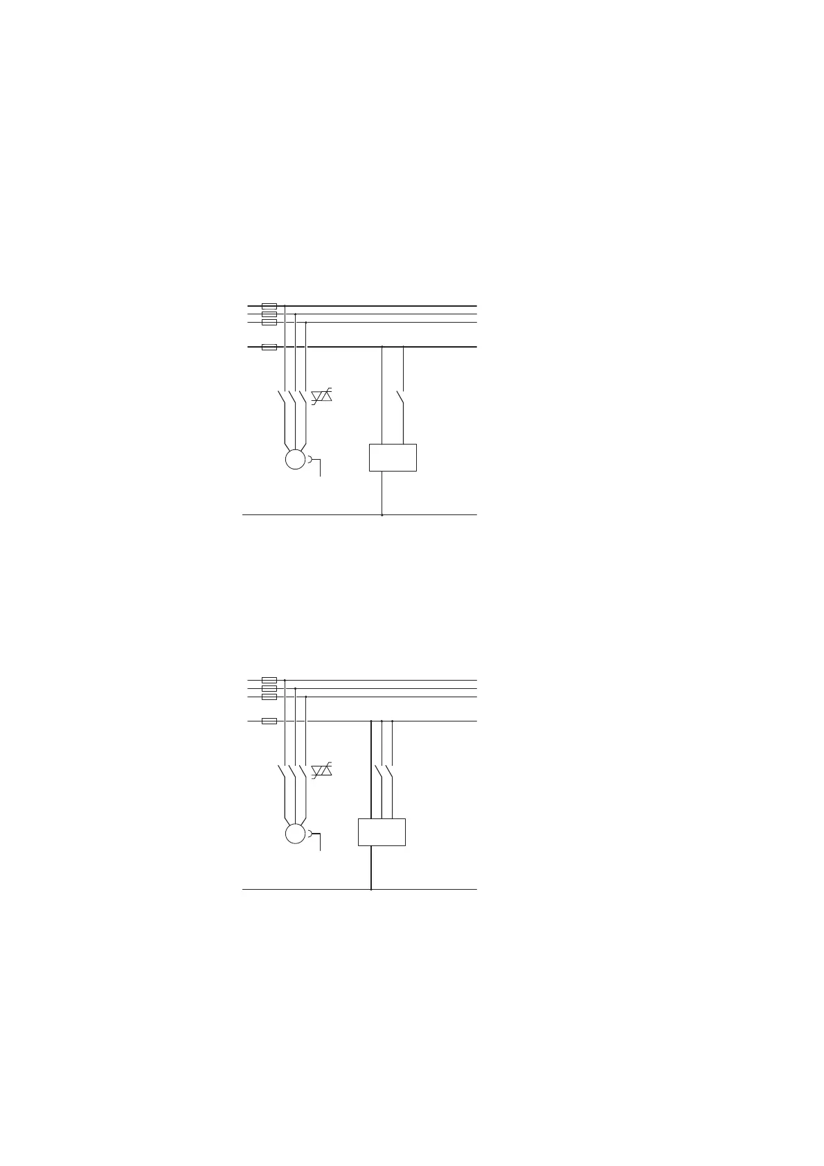
2.1.1 Main and control current paths for EMS-DO-…-24VDC DOL starters
Figure 2: DOL starter
K1 = EMS-DO-…-24VDC
T1 = Clockwise rotation
2.1.2 Main and control current paths for EMS-RO-…-24VDC reversing starters
Figure 3: Reversing starter
K1 = EMS-RO-…-24VDC
T1 = Clockwise rotation
T2 = Anticlockwise rotation
M
3~
A1 ON
L1
L2
L3
+24V DC
M
1
K
1
K
1
PE
L1
F1
F2
F3
T1
T1
L2
T2
L3
T3
GND
A2
M
3~
A1 R L
L1
L2
L3
+24V DC
M
1
K
1
K
1
PE
L1
F1
F2
F3
T1 T1
L2
T2 T2
L3
T3
GND
A2
 Loading...


