2 Engineering
2.3 Safety shutdown with long lifespan
Elektronischer Motorstarter EMS/Electronic Motor Starter EMS 04/15 MN03407009Z-DE/EN www.eaton.com 47
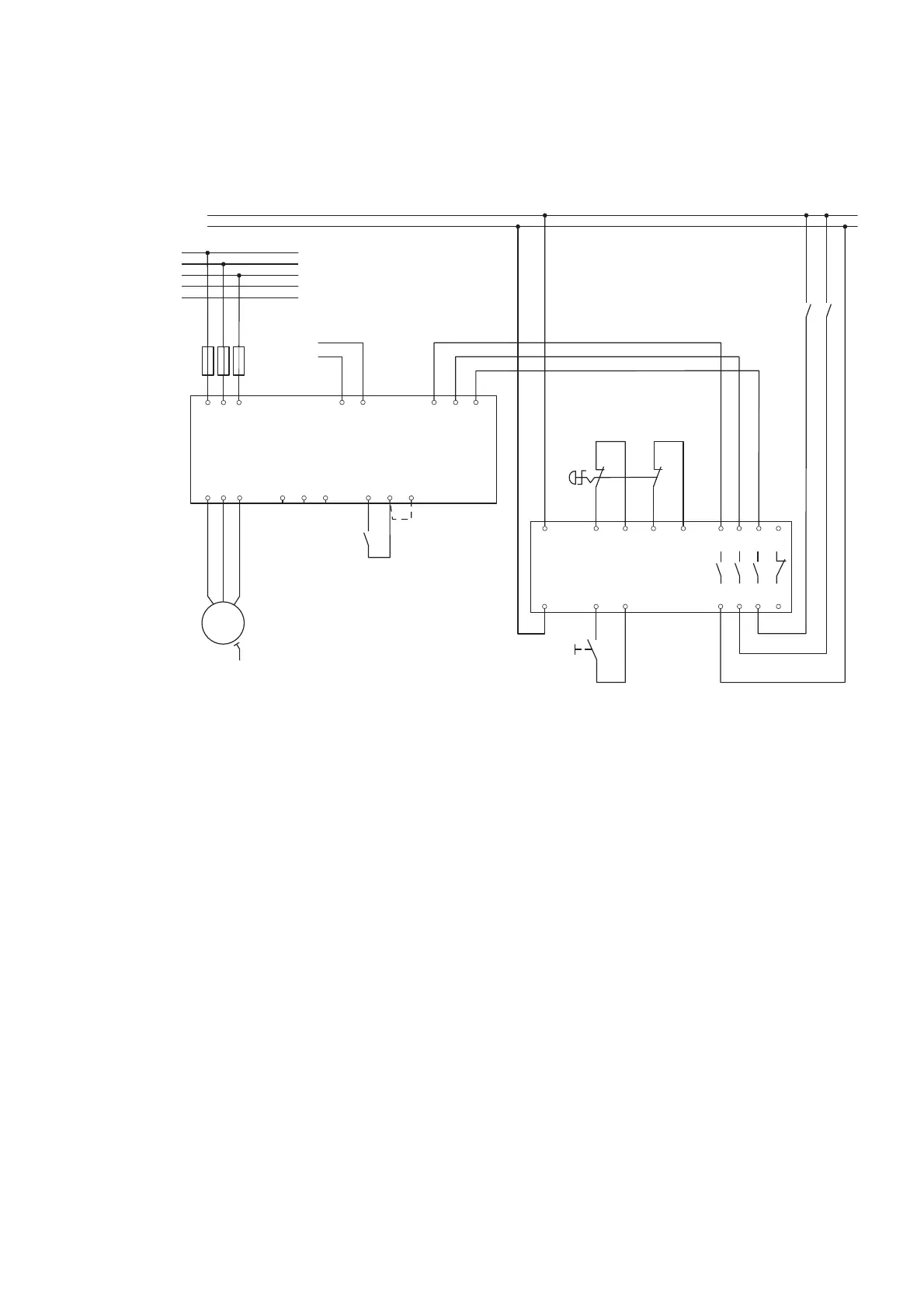
2.3.2 Main and control current path emergency stop (dual-channel)
Figure 7: Main and control current path emergency stop (dual-channel)
S2 = Emergency stop, S3 = Reset
Emergency stop configuration (dual-channel) – (as per cat. 3, SIL 3, PL e):
EMS-ROS-… with higher-level safety relay combination
L1
L2
L3
N
PE
GND
EMS-ROS-...
GND
ESR5-NO-31-24 V AC-DC
24 V DC
F1
3/
L2
1/
L1
A
2
A
1
E R L
5/
L3
24 V DC
2/
T1
4/
T2
6/
T3
95 96 98
M
3 ~
PE
W1V1U1
MAN
RES
AUT
S2
S2
A1 S11 S12 S21 S22
13 23 33 41
A2 S33 S34
14 24 34 42
S3
 Loading...


