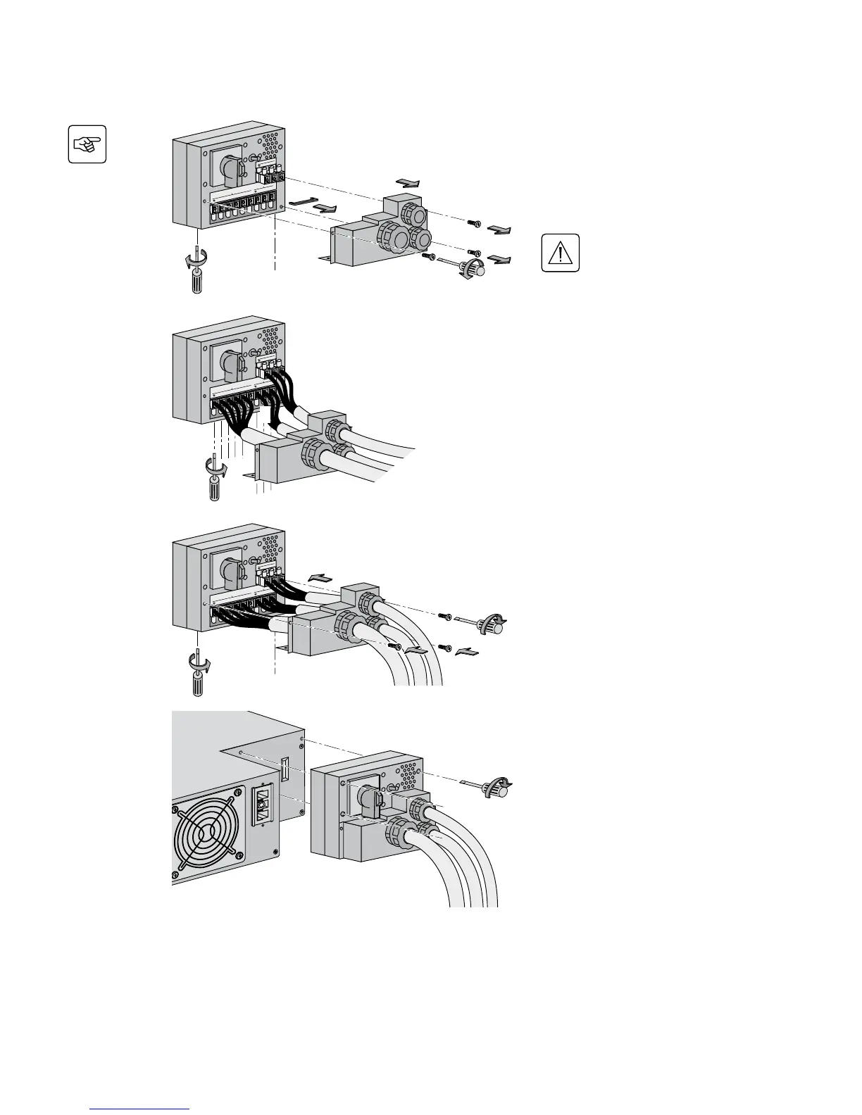
1 - Remove the terminal block cover
(5 screws),
2 - Remove the bridge connected
between L2 and L1,
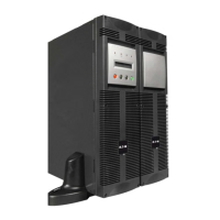
3 - Insert the Normal AC cable through
the cable gland,
4 - Connect the 5 wires to the Normal
AC terminal block,
Always connect the earthing
wire rst.
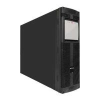
5 - Insert the Output cable to the load
through the Output cable gland,
6 - Connect the 3 wires to the output
terminal block,
7 - Insert the Bypass cable through the
cable gland,
8 - Connect the 3 wires to the Bypass
AC terminal block,
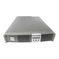
9 - Refit the terminal block cover and
tighten the cable glands,
10 - Secure the junction Input/Output
box to the rear of the power module
by means of the 3 screws.
UPS with separate Normal and Bypass AC sources
2. Installation
1
5
2
4
3
9
6
7
1
1
1
9
9
9
10