8
1
1
1
1
1
1
1
1
1
1
1
1
1
1
1
1
1
1
1
1
MAGNUM PRODUCT GUIDE CA013002EN—April 2017 www.eaton.com54
Accessory devices and connections
•
Auxiliary switch
An auxiliary switch is an optional device providing remote
electrical indication if the circuit breaker is open or closed.
Up to three auxiliary switches can be mounted in one breaker.
Each switch has two normally open (“A”) and two normally
closed (“B”) contacts for a total of 12 available contacts.
Table 17. Auxiliary switch, overcurrent trip switch, and
cell switch contact ratings
Control voltages Contact rating inductive load (amperes)
250 Vac 10
125 Vdc 0.5
250 Vdc 0.25
Auxiliary switch (2A/2B)
Internal electrical accessories
Other electrical accessories are mounted inside the circuit
breaker. They can be factory or site installed. There are three
different internally mounted accessories:
1. Overcurrent Trip Switch (Bell Alarm)
2. Mechanical Trip Flag Pop-out Indicator
3. Motor Operator
•
Overcurrent trip switch (bell alarm)
An overcurrent trip switch (bell alarm) is an optional device.
It provides an electrical indication when a circuit breaker trips
as a result of the trip unit reacting to an overcurrent condition.
Opening as a result of a circuit breaker’s manual open button,
shunt trip, or undervoltage release does not cause the
overcurrent trip switch to operate.
The status of the contacts changes when the trip indicator
pops out. This permits the switch to be used as an alarm or
in conjunction with a spring release to block a subsequent
remote electrical closing signal. Refer to Section 3 for
available options.
•
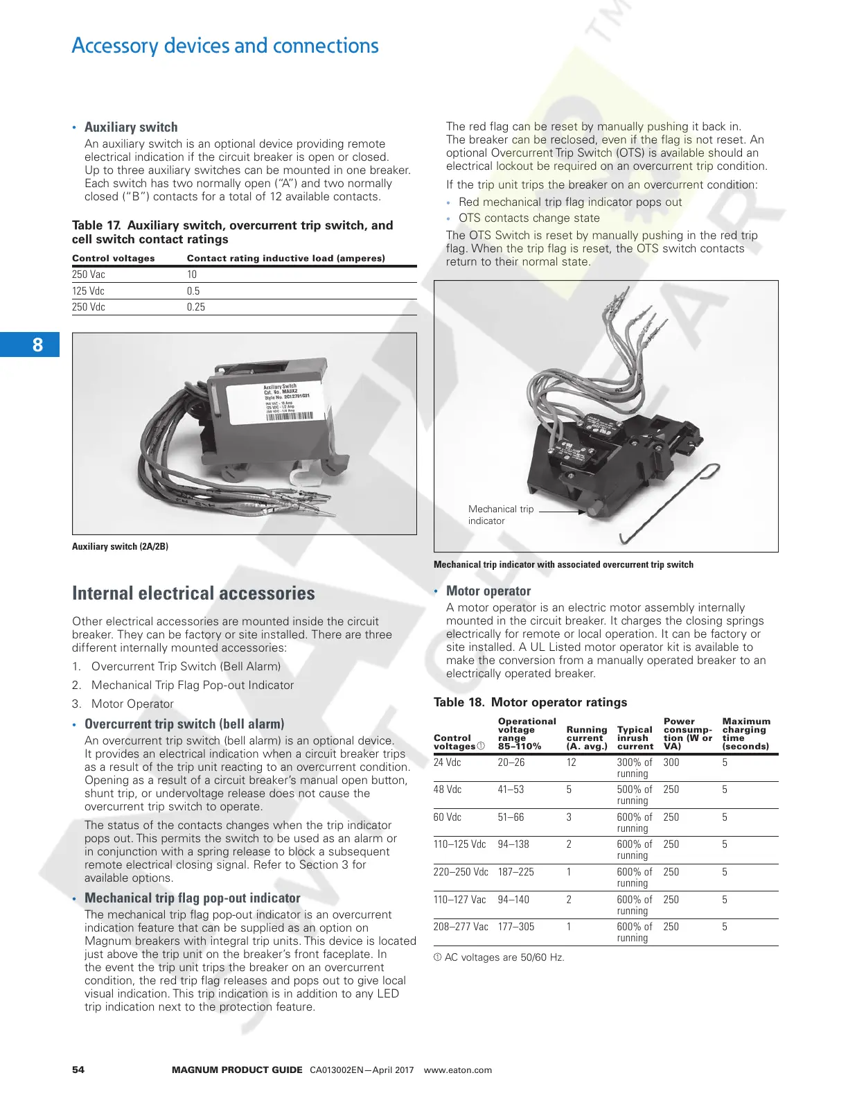
Mechanical trip flag pop-out indicator
The mechanical trip flag pop-out indicator is an overcurrent
indication feature that can be supplied as an option on
Magnum breakers with integral trip units. This device is located
just above the trip unit on the breaker’s front faceplate. In
the event the trip unit trips the breaker on an overcurrent
condition, the red trip flag releases and pops out to give local
visual indication. This trip indication is in addition to any LED
trip indication next to the protection feature.
The red flag can be reset by manually pushing it back in.
The breaker can be reclosed, even if the flag is not reset. An
optional Overcurrent Trip Switch (OTS) is available should an
electrical lockout be required on an overcurrent trip condition.
If the trip unit trips the breaker on an overcurrent condition:
• Red mechanical trip flag indicator pops out
• OTS contacts change state
The OTS Switch is reset by manually pushing in the red trip
flag. When the trip flag is reset, the OTS switch contacts
return to their normal state.
Mechanical trip
indicator
Mechanical trip indicator with associated overcurrent trip switch
•
Motor operator
A motor operator is an electric motor assembly internally
mounted in the circuit breaker. It charges the closing springs
electrically for remote or local operation. It can be factory or
site installed. A UL Listed motor operator kit is available to
make the conversion from a manually operated breaker to an
electrically operated breaker.
Table 18. Motor operator ratings
Control
voltages
Operational
voltage
range
85 –110%
Running
current
(A. avg.)
Typical
inrush
current
Power
consump-
tion (W or
VA)
Maximum
charging
time
(seconds)
24 Vdc 20–26 12 300% of
running
300 5
48 Vdc 41–53 5 500% of
running
250 5
60 Vdc 51–66 3 600% of
running
250 5
110–125 Vdc 94–138 2 600% of
running
250 5
220–250 Vdc 187–225 1 600% of
running
250 5
110–127 Vac 94–140 2 600% of
running
250 5
208–277 Vac 177–305 1 600% of
running
250 5
AC voltages are 50/60 Hz.
1
1
Courtesy of NationalSwitchgear.com

 Loading...