7
1
1
1
1
1
1
1
1
1
1
1
1
1
1
1
1
1
1
1
1
1
MAGNUM PRODUCT GUIDE CA013002EN—April 2017 www.eaton.com48
Magnum trip units and communication devices
Additional modules for Digitrip 1150 trip units
•
Power relay module:
Provides a power supply to
power the Digitrip 1150+
trip unit’s 24 Character LED
display and communications
functions. The Power Relay
Module also provides
(3) programmable relay
contacts for interface with
external equipment. The
power relay module requires
an external customer
supplied voltage source.
Programmable Relay
Contacts via the Digitrip
1150+ trip unit trip and alarm
programming menus:
• Contact A - Pulse Initiator
or Alarm and Trip output
relay
• Contact B - Alarm and
Trip output relay. ARMS
remote indication
• Contact C - Latching type
Alarm and Trip output relay
that holds status upon
loss of auxiliary power.
Alarm Contact Ratings
(resistive load):
• 0.5 Amp at 230 Vac
• 1.0 Amp at 120 Vac
• 1.0 Amp at 24-48 Vdc
•
Potential Transformer
Module (PTM):
The PTM module provides
system line voltage
information to the Digitrip
1150+ trip unit. It provides
signal data to calculate:
• Voltage
• Power
• Energy
• Related Data
The PTM is internally
hard wired in the breaker,
normally to the line side
breaker terminals, except for
a reverse feed configuration.
A white disconnecting plug
is provided to disconnect
the PT Module circuit from
the line voltage during
dielectric testing.
•
Accessory bus:
The accessory bus feature
on the Digitrip 1150+
permits the application
of additional discrete
programmable relay
contacts by using one or
more Digital Relay Modules.
The accessory bus is
connected to secondary
terminals A17 and A18 for
external connections to
the Digital Relay
Modules via twisted pair
communications cable.
•
Digital relay module:
Digital relay modules are
mounted by DIN Rail,
separate from the circuit
breaker. Up to 4 Digital
Relay Modules (addresses
001 to 004) can be applied
per circuit breaker. Each
Digital Relay Module has
relays with form C contacts
rated at 10 amps maximum
at 250 Vdc. A control voltage
source of 120 Vac ±20% or
38-125 Vdc is required to
power each unit.
The Digitrip 1150+ trip unit
can be programmed to
change state of the Digital
Relay Module relay contacts
for any combination of the
following:
• Auxiliary Switch
• Bell Alarm
• Long Delay Trip
• Short Delay Trip
• Instantaneous Trip
• Ground Fault Trip
• Ground Fault Alarm
• High Load Alarm
• Deadman
• Watchdog
• Arc-flash Reduction
Maintenance System
(ARMS) status indication
•
Communication systems
and protocols:
Communication to a host
computer or a Breaker
Interface Module (BIM)
is possible with both the
Digitrip 520MC and Digitrip
1150+ trip units. Network
command and control
communications is achieved
with translators to common
protocols, such as Modbus
®
INCOM
TM
and Profibus
®
and
Ethernet. External power
must be supplied to the
breaker.
Trip unit data is
communicated using
the appropriate protocol
and interface. Modules
catalog numbers PMINT
and MMINT are compact
devices that support
common interfaces, and
are DIN rail mounting.
They output all information
available in the trip unit to
the field bus including:
• Status
• Current
• Voltage
• Power
• Energy
• Diagnostic information
(such as overcurrent,
phase asymmetry and
overvoltage)
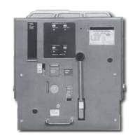
Power relay module
Courtesy of NationalSwitchgear.com

 Loading...