Serial interface (Modbus RTU)
04/10 MN04020001Z-EN
140
Data storage with Modbus
The information is stored in one input and one holding register.
The registers are the memory location of the data. The memory
size of each register is 1 word.
Modbus-Register-Mapping
The register mapping enables the processing in MMX of the
content listed in the following table via Modbus RTU.
Each content in this table is assigned an ID number (abbreviation
of the register numbers). This ID number is used in M-Max
TM
for
the communication with Modbus RTU.
Example: Control word (ID 2001)
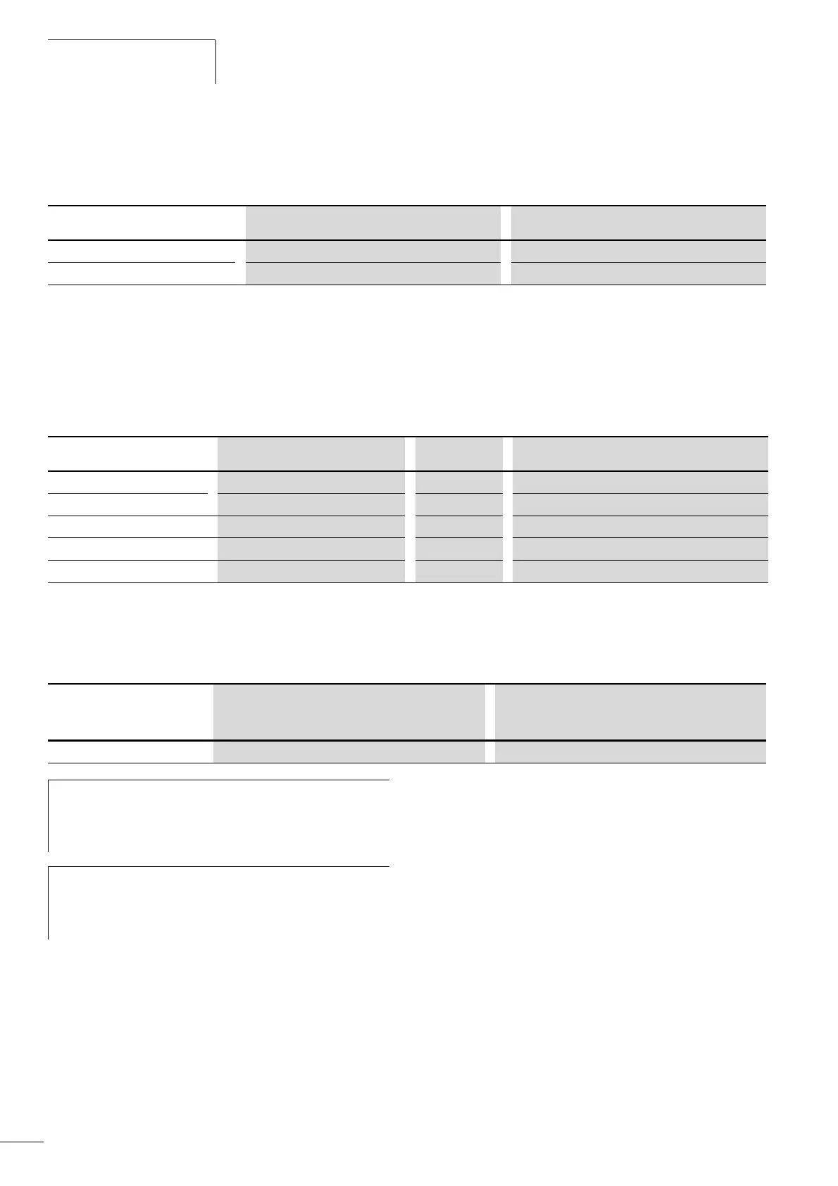
Register numbers Type Name
30001 - 39999 Read only (ro = read only) Input-register
40001 - 49999 Read/write (rw = Read/write) Holding register
Group Register numbers ID range Assignment of the ID numbers
Display values 40001...40098 (30001...30098) 1...98 Parameter list: (a chapter “Appendix”)
Failure code 40099 (30099) 99 Error list: (a chapter 5)
Parameters 40101...40999 (30101...30999) 101...1999 Parameter list: (a chapter “Appendix”)
Input process data 42001...42099 (32001...32099) 2001...2099 (a page 141)
Output process data 42101...42199 (32101...32199) 2101...2199 (a page 142)
ID Register numbers
Value
2001 32001/42001
Application Communication of Modbus RTU Memory location of the data
h
With some PLC manufacturers, the interface driver for
Modbus RTU communication may contain an offset of
+ 1 (the ID to be used would then be 2000 instead of
2001).
h
When processing values, the comma is not included, e.g.
the motor current (ID 2106) in the display of the MMX is
shown as 0.35 A but is transferred via Modbus as
0023 [hex] (0035 [dec])].
 Loading...


