Engineering
04/10 MN04020001Z-EN
28
Motor and Application
Motor selection
General recommendations for motor selection:
• Use three-phase powered asynchronous motors with short-
circuit rotors and surface cooling, also called asynchronous
motors or standard motors for the frequency-controlled drive
system (PDS). Other specifications such as external rotor
motors, slip-ring motors, reluctance motors, synchronous or
servo motors can also be run with a frequency inverter but
normally require additional planning and discussion with the
motor manufacturer.
• Use only motors with at least heat class F (155 °C maximum
steady state temperature).
• 4-pole motors are preferred (synchronous speed: 1500 min
-1
at
50 Hz or 1800 min
-1
at 60 Hz).
• Take the operating conditions into account for S1 operation
(IEC 60034-1).
• When operating multiple motors in parallel on one frequency
inverter, the motor output should not be more than three power
classes apart.
• Ensure that the motor is not overdimensioned.
If a motor in speed control mode is underdimensioned, the
motor rating must only be one rating level lower.
Connecting motors in parallel
The M-Max
TM
frequency inverters allow parallel operation of
several motors in U/f control mode:
• U/f control: several motors with the same or different rated
operational data. The sum of all motor currents must be less
than the frequency inverter’s rated operational current.
• U/f control: parallel control of several motors. The sum of the
motor currents plus the motors’ inrush current must be less than
the frequency inverter’s rated operational current.
Parallel operation at different motor speeds can be implemented
only by changing the number of pole pairs and/or changing the
motor’s transmission ratio.
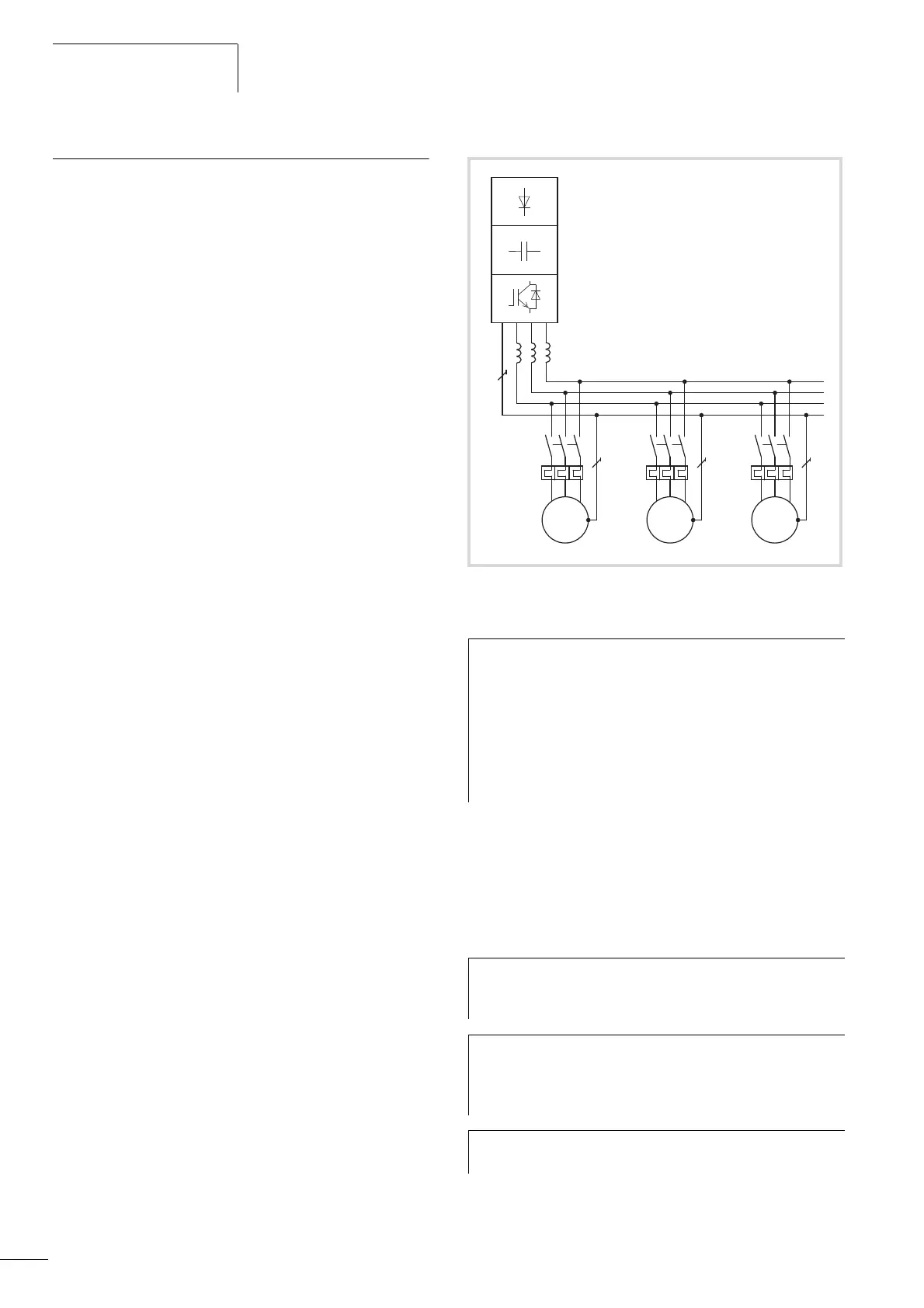
Connecting motors in parallel reduces the load resistance at the
frequency inverter output. The total stator inductance is lower and
the leakage capacity of the lines greater. As a result, the current
distortion is greater than in a single-motor circuit. To reduce the
current distortion, you should use motor reactors (see a in
figure 12) in the output of the frequency inverter (see also Section
“Motor chokes”, page 171).
Figure 12: Parallel connection of several motors to one frequency
inverter
h
Caution!
Debounced inputs may not be used in the safety
circuit diagram.
If you are connecting multiple motors on one frequency
inverter, you must design the contactors for the individual
motors according to utilization category AC-3.
Selecting the motor contactor is done according to the
rated operational current of the motor to be connected.
h
The current consumption of all motors connected in
parallel must not exceed the frequency inverter’s rated
output current I
2N
.
h
Electronic motor protection can not be used when
operating the frequency inverter with several parallel
connected motors. You must, however, protect each
motor with thermistors and/or overload relays.
h
The use of motor protective circuit breaker at the
frequency inverter’s output can lead to nuisance tripping.
Q11
F1
M1
Q12
F2
M2
Q13
F3
M3
U1 V1 W1 U1 V1 W1 U1 V1 W1
M
3
˜
M
3
˜
M
3
˜
 Loading...


