04/10 MN04020001Z-EN
EMC measures
27
Mains contactor
The mains contactor enables an operational switching on and off
of the supply voltage for the frequency inverter and switching off
in case of a fault.
The mains contactor is designed based on the mains-side input
current (I
LN
) of the frequency inverter and the utilization category
AC-1 (IEC 60947). Mains contactors and the assignment to
M-MAX
TM
frequency inverters are explained in the appendix.
EMC measures
Electrical components in a system (machine) have a reciprocal
effect on each other. Each device not only emits interference but is
also affected by it. The interference can be produced by galvanic,
capacitive and/or inductive sources or by electromagnetic
radiation. In practice, the limit between line-conducted
interference and emitted interference is around 30 MHz. Above 30
MHz, cables and conductors act like antennas that radiate
electromagnetic waves.
Electromagnetic compatibility (EMC) for frequency controlled
drives (variable speed drives) is implemented in accordance with
product standard IEC/EN 61800-3. This includes the complete
power drive system (PDS), from the mains supply to the motor,
including all components, as well as cables (see figure 9
page 23). This type of drive system can consist of several individual
drives.
The generic standards of the individual components in a PDS
compliant with IEC/EN 61800-3 do not apply. These component
manufacturers, however, must offer solutions that ensure
standards-compliant use.
In Europe, maintaining the EMC guidelines is mandatory.
A declaration of conformity (CE) refers always to a "typical" power
drive system (PDS). The responsibility to comply with the legally
stipulated limit values and thus the provision of electromagnetic
compatibility is ultimately the responsibility of the end user or
system operator. This operator must also take measures to
minimize or remove emission in the environment concerned (see
figure 11). He must also utilize means to increase the interference
immunity of the devices of the system.
With their high interference immunity up to category C3,
M-MaxTM frequency inverters are ideal for use in harsh industrial
networks (2nd environment).
With line-conducted emission, type MMX…-F… frequency
inverters (with integrated interference suppression filter) ensure
the observance of the sensitive limit values of category C2 in
environment 1. This requires an EMC-compliant installation (see
page 37) and the observance of the permissible motor cable
lengths and maximum switching frequency (f
PWM
) of the inverter.
Type MMX…-N… frequency inverters can comply with the limit
values of category C1 in environment 1 when used in conjunction
with an assigned external interference suppression filter (see
chapter "Appendix", page 161).
The required EMC measures should be taken into account in the
engineering phase. Improvements and modifications during
mounting and installation or even at the installation site involve
additional and even considerably higher costs.
h
While planning the project, make sure that inching
operation is not done via the mains contactor of the
frequency inverter on frequency-controlled drives, but
through a controller input of the frequency inverter.
The maximum permitted operating frequency of the mains
voltage with the M-MAX
TM
frequency inverter is one time
per minute (normal operation).
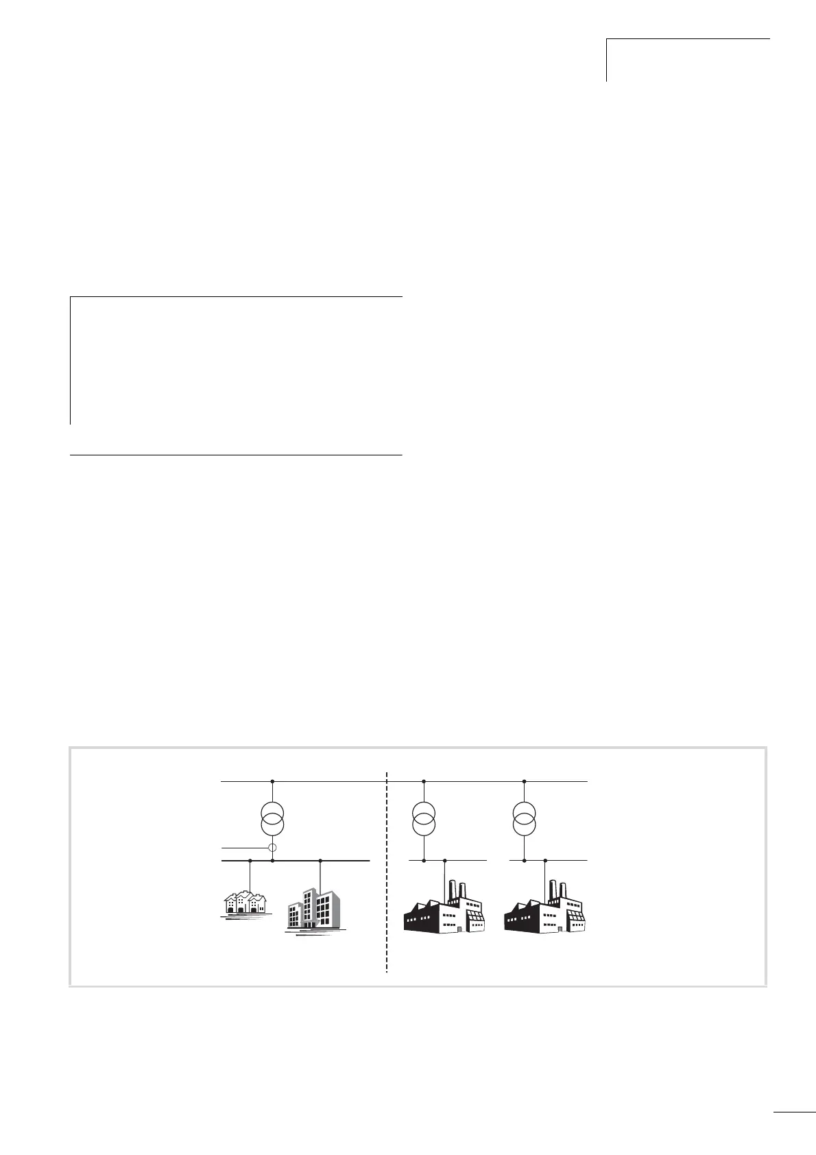
Figure 11: EMC environment and category
Public medium-voltage grid
Public
low-voltage grid
Industrial
grid 1
Industrial
grid 2
Measuring
point
Category C1
Category C1/C2 Category C3/C4 Category C3/C4
1
st
environment 2
nd
environment
 Loading...


