M-Max
TM
Series
04/10 MN04020001Z-EN
20
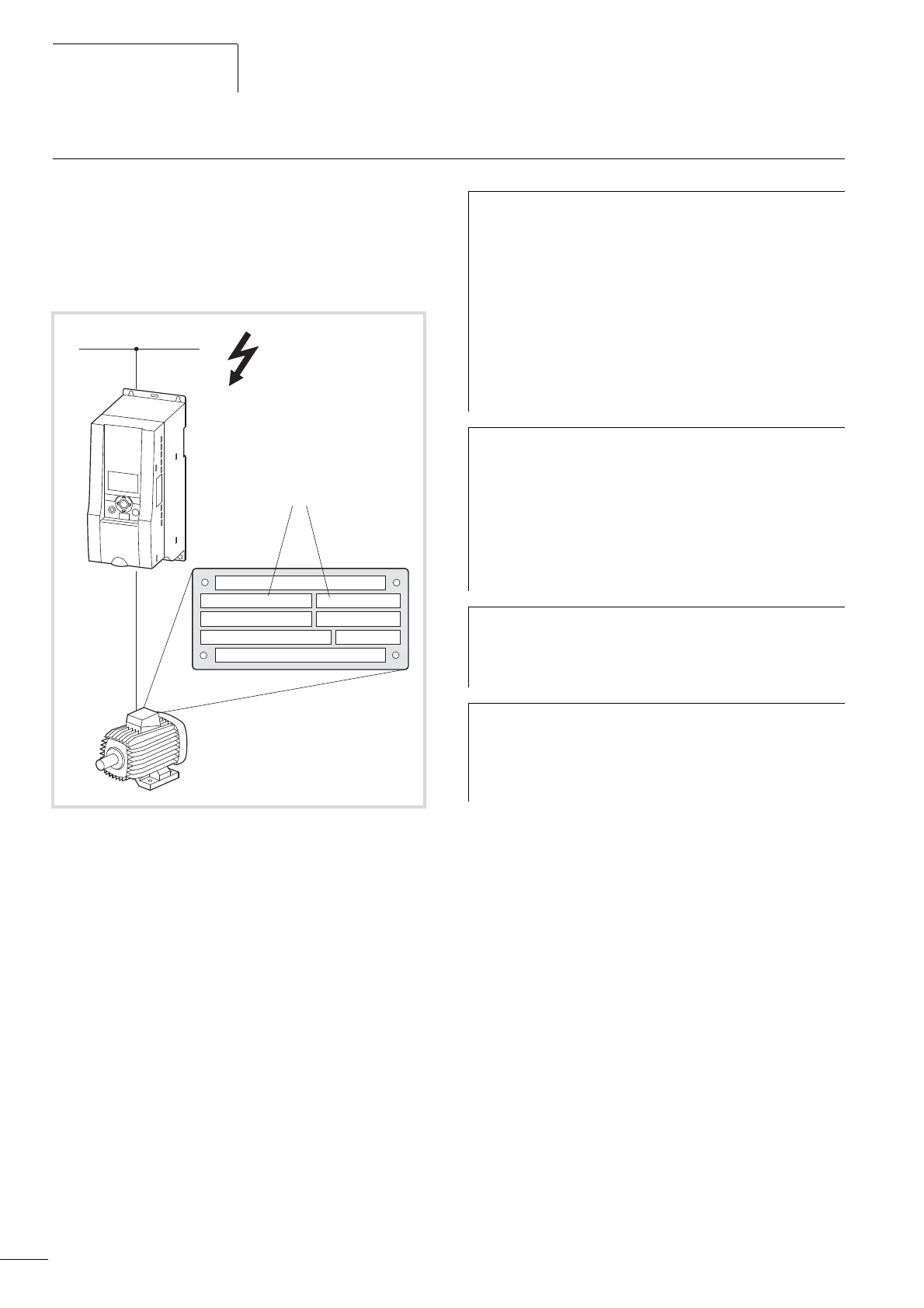
Selection criteria
The frequency inverter c is selected according to the supply
voltage U
LN
of the mains supply a and the rated current of the
assigned motor b. The circuit type (
D / Y) of the motor must be
selected according to the supply voltage a. The rated output
current I
e
of the frequency inverter must be greater than/equal to
the rated motor current.
When selecting the drive, the following criteria must be known:
• Type of motor (three-phase asynchronous motor)
• Mains voltage = rated operating voltage of the motor
(e.g. 3 AC ~ 400 V),
• Rated motor current (guide value, dependent on the circuit type
and the supply voltage)
• Load torque (quadratic, constant),
• Starting torque,
• Ambient temperature (rated value +40 °C).
Figure 8: Selection criteria
230 / 400 V d / Y
4.0 / 2.3
0,75
0.67
j
cos
kW
min
-1
1410 50 Hz
A
b
c
a
U, I, f
I
OK
BACK
RESET
LOC
REM
h
When connecting multiple motors in parallel to the output
of a frequency inverter, the motor currents are added
geometrically – separated by effective and idle current
components. When you select a frequency inverter, make
sure that it can supply the total resulting current. If neces-
sary, for dampening and compensating the deviating
current values, motor reactors or sinusoidal filters must be
connected between the frequency inverter and the motor.
The parallel connection of multiple motors in the output
of the frequency inverter is only permitted with U/f-char-
acteristic curve control.
h
If you connect a motor to an operational frequency
inverter, the motor draws a multiple of its rated
operational current. When you select a frequency inverter,
make sure that the starting current plus the sum of the
currents of the running motors will not exceed the rated
output current of the frequency inverter.
Switching in the output of the frequency inverter is only
permitted with U/f-characteristic curve control.
h
The speed control with slip compensation (P11.8)
increases the drive dynamics and optimizes the output.
For this the frequency inverter processes all motor data in
an electrical image.
h
The speed control operating mode (P11.8) must only be
used with single drives (one motor at the output of the
frequency inverter). The rated current of the motor must
be assigned to the rated operational current of the
frequency inverter (same rating).
 Loading...


