04/10 MN04020001Z-EN
Commissioning with control
signal terminals (factory
setting)
57
Commissioning with control signal terminals (factory
setting)
M-Max
TM
frequency inverters are set in the factory and can be
started directly via the control signal terminals by connecting the
motor outputs allocated for the mains voltage (see connection
example below).
The following shows a simplified connecting example of a
connection with default settings.
Connect the frequency inverter according to the connection
example for the simple commissioning with the specified default
settings (see connecting example above).
When the specified power supply is applied to connection terminal
L2/N and L3 (MMX11) or L1 and L2/N (MMX12) or L1, L2/N and
L3 (MMX32, MMX34), the LCD display lights up and all segments
are displayed briefly.
The frequency inverter runs a self-test automatically when the
power is applied.
The arrows (
D) in the top status line of the LCD display show the
operating status:
• READY = proper operating status
• STOP = stop (no start command)
The arrows (
C) in the bottom status line show the controller
commands. Actuation is done via the control signal terminals (I/O
= Control Input/Output) in the factory setting.
The FWD mark (Forward) designates the basic rotational direction
(phase sequence for a clockwise rotating field) on connection
terminals U/T1, V/T2 and W/T3.
The operating data of the output frequency is shown in the LCD
display in alternating sequence with M1.1 and 0.00 Hz. The arrow
Y in the left-hand status line indicates menu level MON (Monitor
= Operating data display).
h
You can skip this section if you want to set up the
parameters directly for optimal operation of the frequency
inverter based on the motor data (rating plate) and the
application.
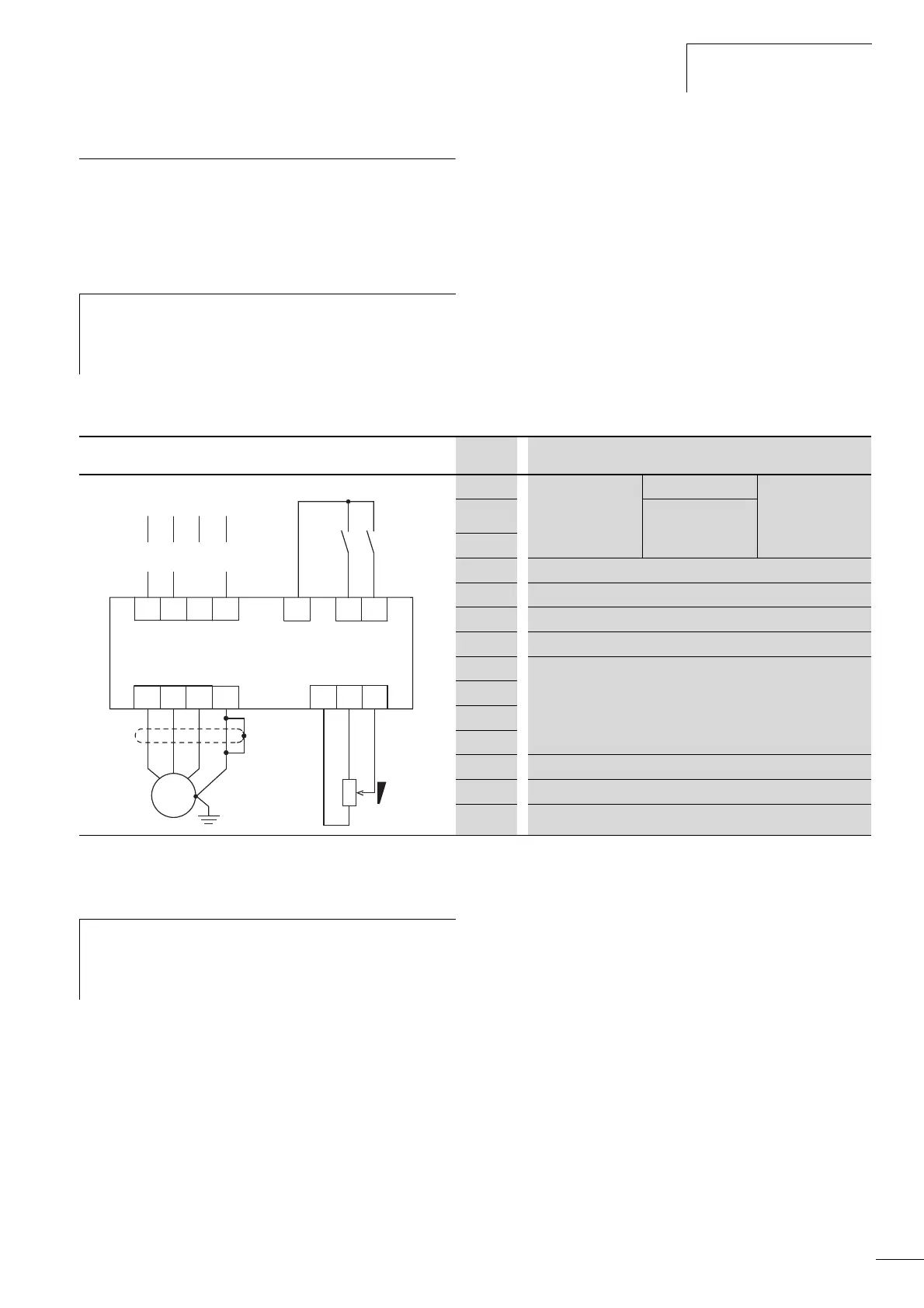
Circuit example Terminal Designation
L1 Single-phase mains
connection
(MMX12)
- Three-phase mains
connection
(MMX32, MMX34)
L2/N Single-phase mains
connection
(MMX11)
L3 -
PE Ground connection
6 Control voltage +24 V (output, maximum 50 mA)
8 FWD, Start release clockwise rotating field
9 REV, Start release left rotating field
U Connection for three-phase ac motor
(three-phase motor)
V
W
PE
3 Setpoint value voltage +10 V (Output, maximum 10 mA)
1 Reference potential GND (0 V)
2 Frequency setpoint f-Set (Input 0 – +10 V)
PE
PE
PE
PE
WVU
M
3 ~
e
123
6 89
24 V
FWD
0...+10 V
L3L1
L2/N
L1
N
L3L1
L2
REV
f-Soll
h
If the connections for the setpoint value potentiometer
cannot be clearly allocated with terminals 1, 2 and 3, you
should set the potentiometer to about 50% before giving
the start release (FWD/REV) for the first time.
 Loading...


