04/10 MN04020001Z-EN
67
6 Parameters
Control unit
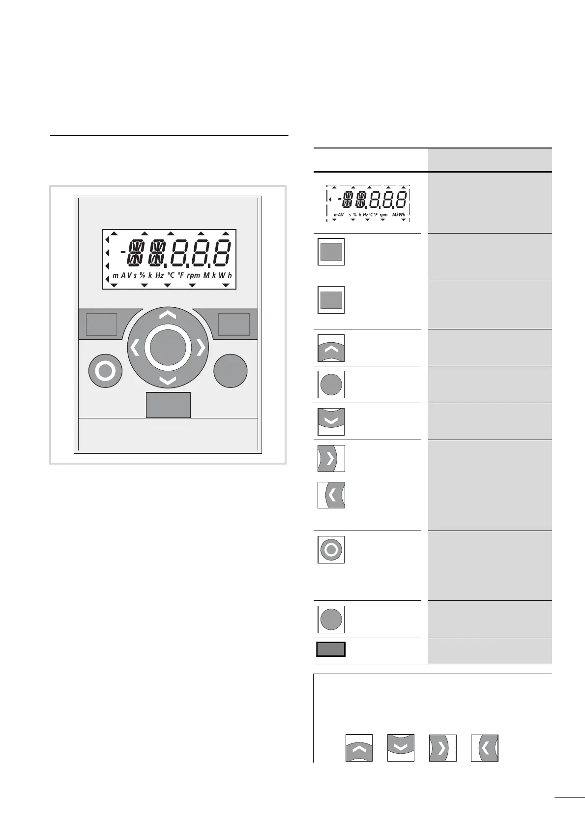
The following figure shows and indicates the elements of the
M-Max
TM'
s integrated control unit.
Table 6: Control unit elements
Figure 63: View of the keypad with LCD display, function keys and
interface
LCD = Liquid Crystal Display
I
BACK
RESET
RUN STOP ALARM FAULTREADY
REF
FWD REV I/O KEYPAD BUS
MON
PAR
FLT
LOC
REM
OK
Operating unit element Explanation
• Backlit liquid crystal display
(LCD).
• Plain text with alphanumeric
characters.
• Acknowledge fault message
(Reset)
• Activates the selection for the
menu levels (
Y flashes).
Move between different control
levels (I/O - KEYPAD - BUS)
according to parameter settings
P6.1 and P6.17.
• Select function and parameter.
• Increase numerical value.
• Confirm and activate selection
(store).
• Lock display.
• Select function and parameter.
•Reduce numerical value
• Move to the individual parameter
groups (… S4.1 - P1.1 - P2.1 -
P3.1 …).
• In displays with several digits
move between the individual
digits (Cursor).
• Direction reversal (FWD n REV)
in KEYPAD mode.
• Stops the running motor (P6.16).
• Reset: Holding down the button
for 5 seconds causes the default
settings to be loaded. All
parameters are reset and the fault
memory (FLT) is cleared.
Motor start with selected direction
of rotation (only active in KEYPAD
control level).
Interface for communication
(Option: MMX-COM-PC).
h
Pressing the arrow buttons increases or decreases the
active value, the parameter or function by one unit.
Holding down an arrow button makes the change
automatically.
RUN STOP ALARM FAULTREADY
REF
FWD REV I/O KEYPAD BUS
MON
PAR
FLT
 Loading...


