For Sales and Support, Contact Walker EMD • Toll-free: (800) 876-4444 • Tel: (203) 426-7700 • Fax: (203) 426-7800 • www.walkeremd.com
NFX9000 Adjustable Frequency Drives
2-2
For more information visit: www.EatonElectrical.com
MN04002003E
February 2006
● Use power terminals R/L1 and S/L2 for single-phase connection to models:
NFXF25A0-1, NFXF50A0-1, NFXF25A0-2, NFXF50A0-2 or NFX001A0-2.
●
Use power terminals R/L1, S/L2 and T/L3 for three-phase connection to models:
NFXF25A0-2, NFXF50A0-2, NFX001A0-2 or NFX002A0-2.
●
Single-phase power must not be used for model NFX002A0-2.
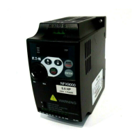
Figure 2-2: Main Circuit Wiring
Single-Phase Models
Input from R/L1, S/L2
LED Display
AC Line
Input
Terminals
Grounding
Frequency
Setting Knob
RUN/STOP
Signal Selection
for AVI to Input
DC0 to +10V or
4 to 20 mA
Control Terminal
RS-485
Communication
Port
Motor Capacity
and Input Power
Data Confirmation
Key
Function Display
Key
UP/DOWN
Grounding
Motor
Connections
Wire Gauge: 12 – 20 AWG
Torque: 5 Kgf-cm
Wire Gauge: 12 – 20 AWG
Torque: 5 Kgf-cm
RA RC +10V AVI D1
U/T1 V/T2 W/T3
R/L1 S/L2 T/L3
D2 D3 D4 GND
STOP
RUN
FWD
REV
RUN
STOP
ENTER
MODE
RESET
WARNING
MIN. MAX.
NFX9000
RS-485
230V 1 PHASE
0.5 HP
!
 Loading...


