IO1—3 x DI, 3 x DO, 1 x Thermistor, 24 Vdc/EXT Option Card
12 PowerXL DG1 Series Option Cards MN040007EN—April 2014 www.eaton.com
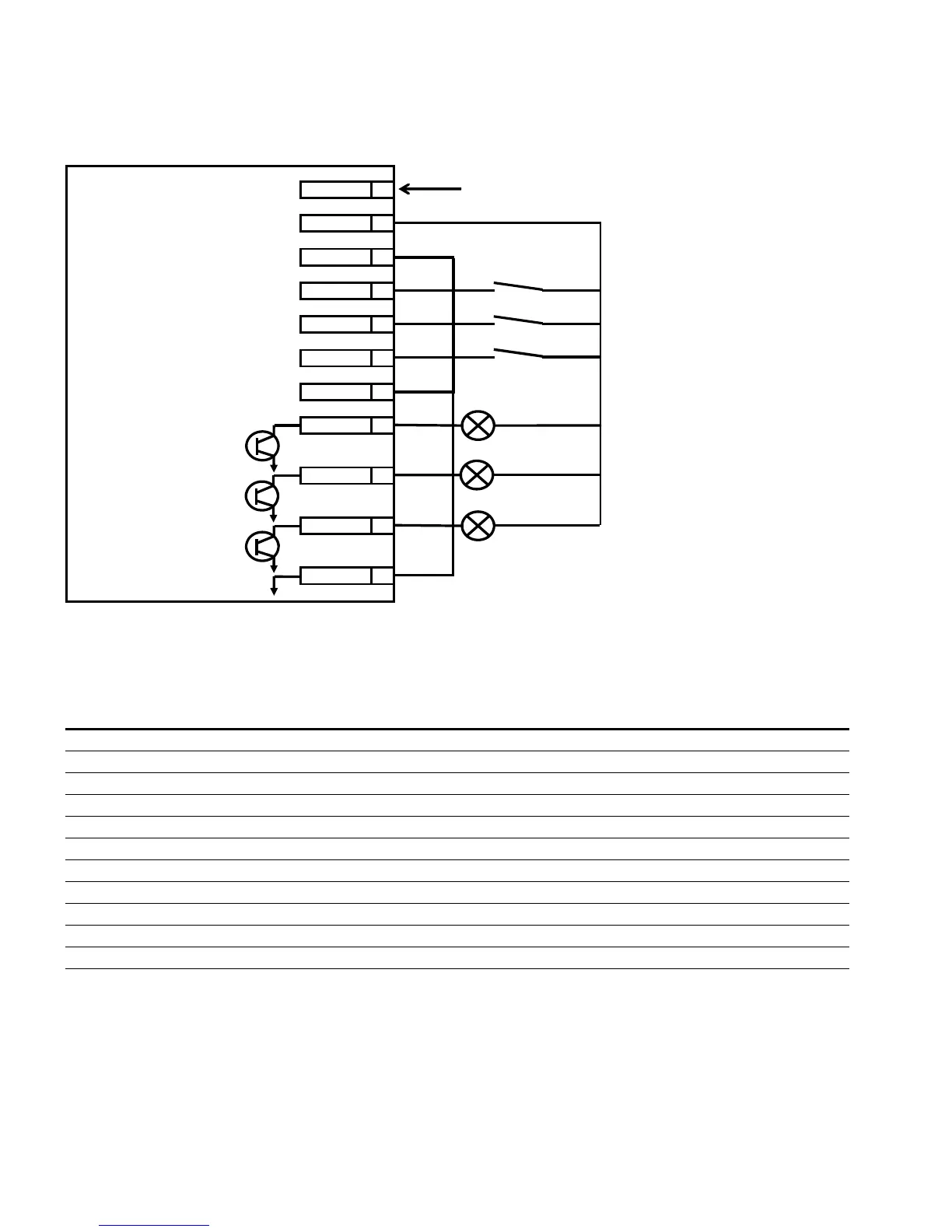
Figure 9. IO1 Board Wire Layout
Note: If the thermistor inputs are selected, it removes 2 of
the digital inputs to be used as the thermistor inputs.
Table 8. IO1 Control Terminals
Notes
1. CMIN is Digital Input Common Line. Sink and Source
available. Digital Input is isolated from 24 Vdc_IN, 24
Vdc_OUT and GND.
2. CMO is Digital Output ground. Digital Output is isolated
from 24 Vdc_IN, 24 Vdc_OUT and GND.
3. Thermistor input on DI2 and DI3 is switched by Relay.
When Thermistor function is turned on, TI1+ is
combined with DIN2 and TI1– is combined with DIN3.
4. Total combined load on available 24 Vdc out terminals
for all optional cards must not exceed 250 mA. The
maximum load on the 24 Vdc out per board is 150 mA.
IO1 Board
DIN1 8
24VDC_IN 11
24VDC_Out 10
GND 9
CMO 1
DIN2/TI1+ 7
DIN3/TI1- 6
DO1 4
CMIN 5
24V DC input
DO2 3
DO3 2
Terminal Signal Technical
1 CMO Digital output common
2 Digital Output 3 Open collector, 50 mA / 36V
3 Digital Output 2 Open collector, 50 mA / 36V
4 Digital Output 1 Open collector, 50 mA / 36V
5 CMIN For digital input
6 Digital Input 3 24V
7 Digital Input 2 24V
8 Digital Input 1 24V
9 Ground Ground for 24 Vdc IN / 24 Vdc OUT
10 24 Vdc OUT Control voltage output; voltage for switches etc.; max. current 150 mA; short-circuit protected
11 24 Vdc IN 24 Vdc input

 Loading...


