UPS-MOUNTED BYPASS SWITCH INSTALLATION
EATON Powerware
®
9155 UPS (8–15 kVA) User’s Guide S 164201553 Rev F www.powerware.com
26
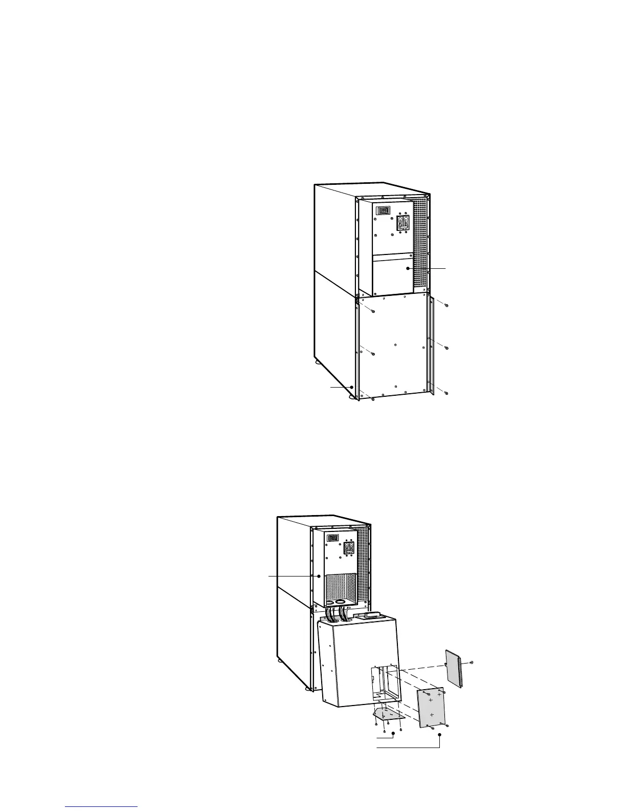
3. Attach the supplied L-bracket to the lower rear (for 2-high) or middle rear (for
3-high) cabinet using three screws (see Figure 15).
Repeat for the other side.
4. Remove the UPS wiring access cover and retain.
L-Bracket and Screws
UPS Wiring
Access Cover
Figure 15. Attaching the L-Brackets
5. Remove the MBM/PDM wiring access cover and one of the conduit landing
plates and retain.
6. Tilt the top of the module forward and slide the module onto the L-brackets. The
top left flange on the module fits up under the UPS electronics unit through an
access slot.
MBM/PDM Wiring
Access Cover
UPS Electronics
Unit
Conduit Landing Plates
Figure 16. Installing the MBM or PDM (MBM Shown)