Do you have a question about the Eaton PXR10 and is the answer not in the manual?
Covers electrical dangers and safety precautions for working with electrical voltage.
Outlines essential steps and precautions to take before starting installation work.
Details the changes and updates made to the manual over different publication dates.
Identifies the intended audience for this manual, specifying required qualifications.
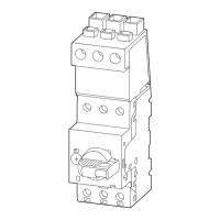
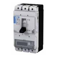
Provides an overview of the PXR electronic trip unit's role in NZM circuit breakers.
Explains the operational principles and components, including current measurement.
Lists the relevant standards and certifications the PXR trip units comply with.
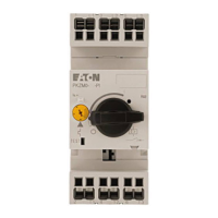
Describes the user interface elements on the trip unit, including switches and displays.
Details the use of the Micro-USB port for configuration and monitoring with software.
Explains the meaning of the status LED, including normal operation and fault conditions.
Describes how trip reasons are indicated on PXR20 units and via LCD on PXR25.
Explains the function of the overload LED on PXR10/PXR20 and adjustment on PXR25.
Details the purpose and features of the tamper-proof cover for settings protection.
Lists the available functions for various PXR trip unit types in a comparative table.
Details the various protection functions like overload, short-circuit, and ground-fault.
Explains the measurement capabilities of the PXR trip unit, depending on the version.
Lists the power and energy values that can be measured by the trip unit.
Refers to external software for evaluating time/current characteristics of PXR trip units.
Explains the necessity and method of connecting a voltage tap for accurate energy metering.
Details the settings and functionality of the overload release (Ir) for the PXR trip unit.
Covers settings for short-time delayed and instantaneous short-circuit releases (Isd, Ii).
Explains ground-fault, override, maintenance mode (ARMS), and ZSI functions.
Covers overload pre-warning, thermal memory, and residual-life indicator functions.
Describes the optional Modbus RTU module for communication via RS485.
Introduces CAM modules for connecting to fieldbus networks like EtherNet/IP, EtherCAT, Profinet.
Discusses external power supply requirements and electromagnetic compatibility considerations.
Covers the integrated real-time clock and the Power Xpert Protection Manager (PXPM) software.
Details the functions and connections provided by the interface module for various trip units.
Explains the optional relay module with two outputs for command and signaling purposes.
Describes how to perform remote testing using PXPM software via USB communication.
Outlines requirements for testing ground-fault protection systems according to regulations.
Explains how to display and configure Modbus module settings via USB or software.
Details the register map, communication protocol, and supported function codes.
Describes the ECAM-IP module for expanding capabilities into EtherNet/IP networks.
Details the ECAM-ECT module for expanding capabilities into EtherCAT networks.
Introduces the ECAM-PNET module for expanding capabilities into Profinet networks.
Provides a table with common faults, their probable causes, and suggested solutions for troubleshooting.
Illustrates the menu structure for accessing measurement data, events, and diagnostic information.
Shows navigation for protection settings, unit settings, language, COM protocols, and device parameters.
| Brand | Eaton |
|---|---|
| Model | PXR10 |
| Category | Circuit breakers |
| Language | English |