31
PTO Interface
Medium- and Heavy-Duty Gen 2 - PTO Inputs and Configurations
Countershaft and Split Shaft PTOs
Electrical Interface Requirements
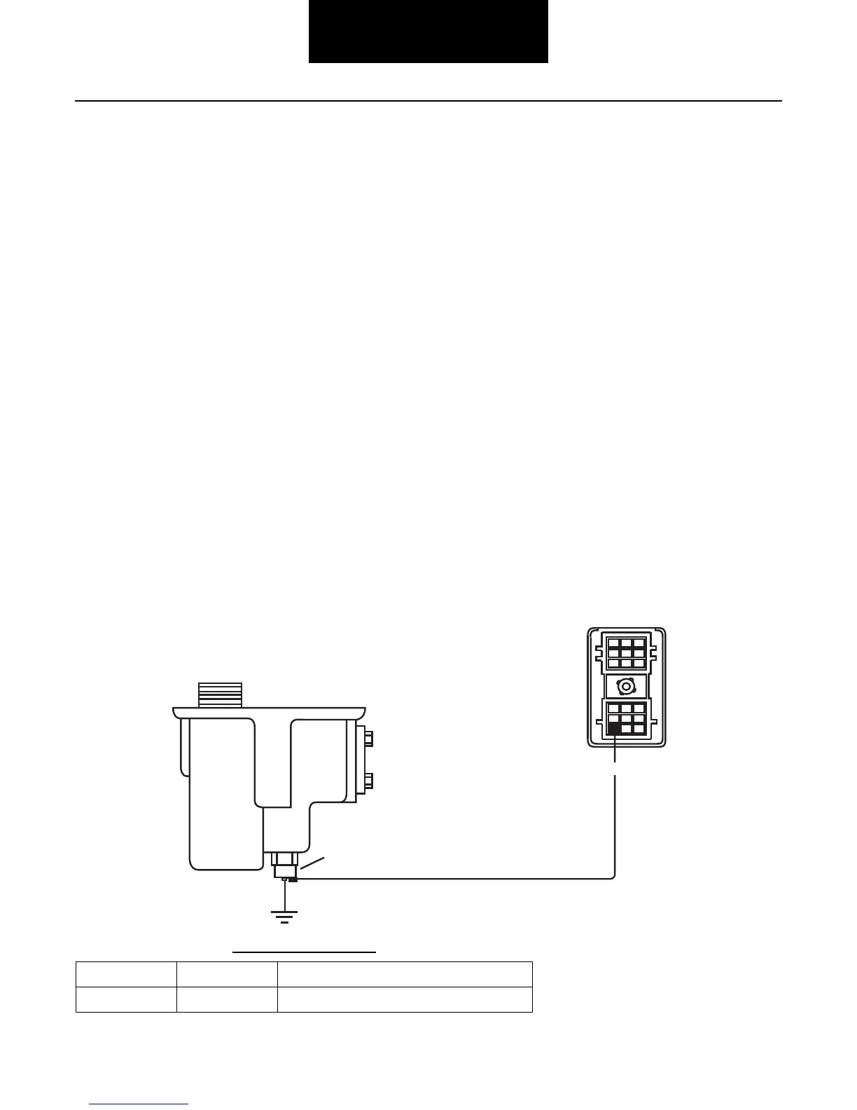
All countershaft-driven Power Take-Offs mounted on Fuller
®
UltraShift ASW transmissions must provide an electrical interface
with the transmission. The PTO-mounted switch is used to activate the PTO operating mode of the transmission. This feature
uses pin F1 of the 18-way transmission connector. See figure below for countershaft-driven PTO electrical interface diagram.
The Fuller UltraShift ASW transmission must have an input signal from the countershaft-driven Power Take-Off when
it is active.
In this active state, the clutch is engaged to drive the transmission main box countershaft. Incorrect or no PTO interface signal to
the transmission will result in no clutch activation and therefore, no PTO operation.
The active signal will illuminate the “Mode” indicator on the push button console.
The transmission default mode for the pin F1 input is for countershaft PTO operation. If the
push button console is programmed
for something other than countershaft PTO operation the PC-based service tool, ServiceRanger, must be used to enable the
countershaft PTO feature.
The
input signal wire for the PTO must be isolated from other PTO-related circuits.
The ground connection must be isolated from local power device ground returns. Frame rail ground is not recommended.
Switch
CounterShaft PTO
D
E
F
123
A
B
C
123
Vehicle Interface
18-way Connector
F1
(Transmission ECU
side of connector)
Interconnection Table
FROM TO Description
F1 PTO+ PTO+
 Loading...