35
PTO Interface
UltraShift
®
PLUS and FA - PTO Inputs and Configurations
Countershaft, Thru-Shaft®, and Split Shaft PTOs
In any case a PTO is used, regardless of PTO style, Eaton requires the OEM provide a “PTO active” input to the transmission ECU.
The vehicle interface harness shall be pre-populated at the ECU 38-way connector with wiring and a connector needed to connect
the PTO. This connector will contain the input and return wire necessary to support the input function.
Note: Must use a
dedicated return on pin 34, frame grounds are not acceptable.
Note: Refer
to Cable and Harness Construction section for correct wire and terminal pin sizes for communication and control
wires.
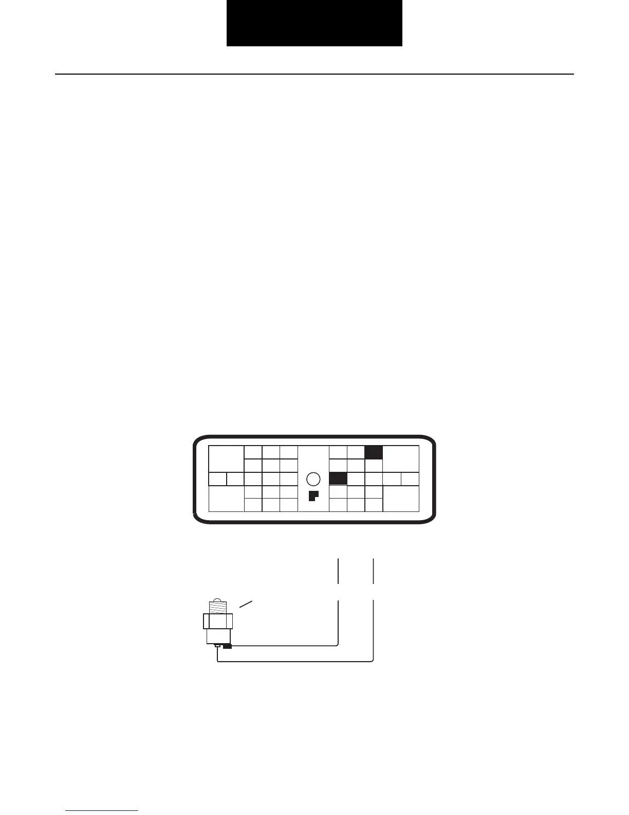
• PTO input shall be a normally open switch.
• The switch shall close to the PTO
return line (pin 34) whenever the PTO is activated. This input activates the PTO mode
of the transmission. This feature uses pin 18 and 34 of the transmission connector, see illustration.
• The input signal wire for the PTO shall be isolated from other PTO related circuits.
• The ground connection shall be isolated from local power device ground returns.
• Proper wiring
ensures the clutch stays engaged during PTO operation and clutch engagement rate is slower.
24
29 30
15 16
26
20
32 33
19
7
3
89
1 26
11 12
4 5
22
21
38
36
37
13 14
35
10
17
23
Front View
Transmission ECU Connector
(Vehicle Interface)
31
25
28
27
18
Pin Side View
34
Switch
34
18
Ground
 Loading...