42
PTO Interface
PTO Interface
Medium-Duty Hybrid - PTO Inputs and Configuration
Eaton recommends the OEM provide a connector and wiring coming from the Hybrid Control Module 38-Way (Vehicle Interface)
with the PTO wires installed.
Note: Connector used must be compatible with 18
TXL.
Note: Refer to Cable
section for correct wire and pin sizes.
Countershaft PTOs
Option 1 - ePTO selection input comes from the Push Button Shift Control, which is sent from the TECU over J1939 to the HCM.
The transmission is confirmed in neutral and this message is sent to the vehicle Body or Chassis controller, which enables the
PTO and then provides feedback to the HCM.
Option 2 - ePTO selection input com
es from the Push Button Shift Control, which is sent from the TECU over J1939 to the HCM.
The transmission will go to neutral and then the HCM will activate PTO pins 21 and 22, which enables the PTO. The PTO switch is
grounded whenever the PTO is activated. This input (active when pin 18 is shorted to ground) verifies the countershaft PTO oper-
ation.
Note: T
he active signal will illuminate the “ePTO” indicator on the Eaton Push Button Shift Control.
The PTO request signal from the Push Button Shift Control will only be available on J1939. Any devices that require the PTO
stat
e must be compatible with J1939.
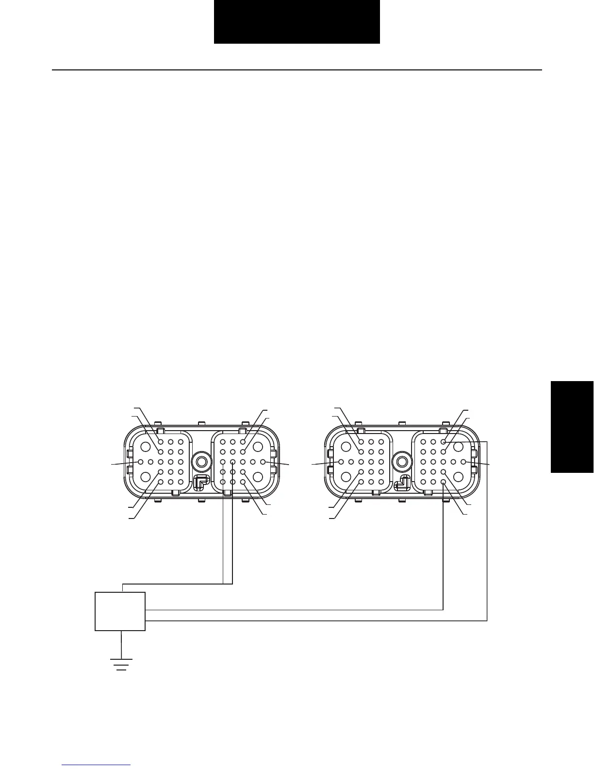
Front View
HCM Connector
(Vehicle Interface)
PTO Power Plus
PTO Power Minus
PTO State
37
38
35
36
1
6
7
12
13
22
23
28
29
34
Front View
(HCM - Hybrid System Interface Connector)
37
38
35
36
1
6
7
12
13
22
23
28
29
34
PTO Signal
 Loading...