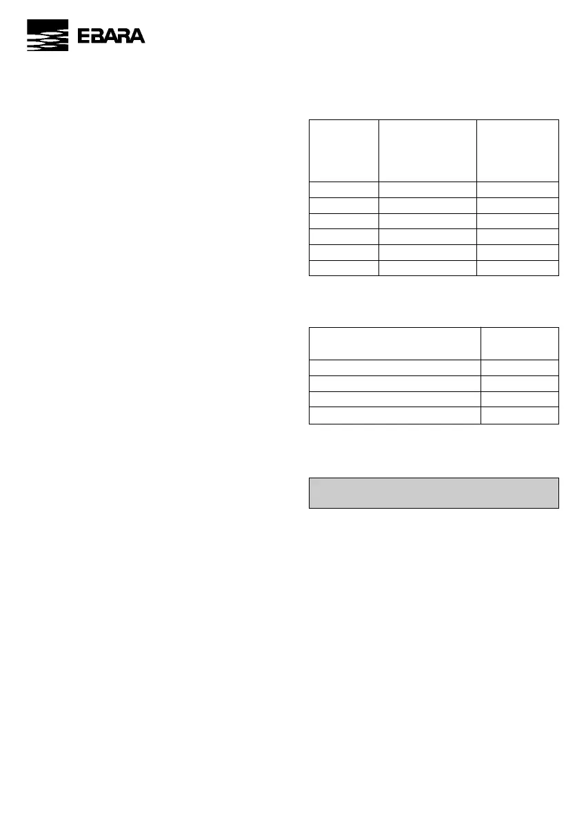
TAB.1: Classification of the maximum surface tem-
perature for apparatuses belonging to group II G (in
accordance with the EN 13463-1 norm)
Temperature Maximum pump Gas or vapour
classification surface mix
temperature ignition
(C°) temperature (°C)
T1 450 >450
T2 300 >300
T3 200 >200
T4 135 >135
T5 100 >100
T6 85 >85
TAB. 2: Maximum temperature of the fluid in accor-
dance with the temperature classification
Maximum temperature of the fluid Temperature
[°C] classification
120 *) T1
120 *) T2
120 *) T3
80 T4
*) Technical datum given in paragraph 7.1 of the
User and Maintenance Manual of the EVM product.
Please refer to paragraph of the instruction booklet
for information on maintenance and repairs.
In addition, the pump must never be cleaned using
dry cloths (rubbing with dry cloths made of pure
polyamide material or cotton, for example, can cau-
se electric discharges).
Some EVM pump models have a bearing on the joint.
No maintenance needs to be carried out on the bea-
rings, which should work for 10,000 hours at a tem-
perature of 40°C without problems.
When replacing or controlling the bearings, the user
must contact the retailer or the help service. The sa-
me is true for the seal (para. 7.2).
Verify, proportionally to the operation conditions,
that the compression ratio is lower than the sponta-
neous ignition limit of the processed fluid.
Correct motor alignment is indispensable for preven-
ting vibrations and faulty bearings.
10 – EVM
Correct assembly of the fluid monitoring device insi-
de the pump ensures that the seal is always lubrica-
ted by the fluid during operation.
Under these conditions, the seal is guaranteed for
continuous 24-hour operation for 6 months.
When replacing or controlling the seal, please refer
to the retailer or the help service.
7.3. PUMP OPERATION WITH AN OBSTRUC-
TED/CLOSED DELIVERY VALVE
FIGURE 5 shows the assembly drawing of the flow
rate measurer (Mp) which must be assembled at de-
livery so that the pump (P) blocks when the flow ra-
te falls below 5% of the maximum return point. In
this case the electric contact (C) deactivates/activa-
tes, disconnecting the electric power supply and ren-
dering the pump safe.
This value guarantees respect of temperature classi-
fication on the internal and external surfaces of the
pump.
7.4. DAMAGE CAUSED BY CHEMICAL NON COM-
PATIBILITY BETWEEN LIQUID AND COMPO-
NENTS
Check the chemical compatibility between the fluid
and the pump parts.
7.5. CAVITATION
It is important to always check correct pump sizing
(therefore it is essential to verify the value needed by
the pump using the NPSH curves. These curves can
be found in the product general catalogues).
7.6. HOT FLUIDS
TAB. 2 gives the maximum temperature that the fluid
can reach in each temperature classification (these
values are permitted respecting the conditions ex-
pressed in point 5.3 NOTES).
It is important to install a reading device in order to
guarantee the maximum temperature of the fluid.
Should the limit value indicated in TAB. 2 be excee-
ded, a release apparatus should switch the pump off.
The temperature measuring instrument must be in
conformity with the UNI EN 13463-1 norm (category
4 of the Machines Directive) and carry an ATEX
marking that is compatible with that of the pump.
The switchboard which guarantees intervention
when the limit values are exceeded must be FAILU-
RE SAFE.
8. MAINTENACE AND REPAIRS