LX20B – Manual Page 10 / 67
Connections of wires shall be made with due care to prevent any faults or dead
shorts. Places of connections shall be protected against weather conditions. For
safety reasons, on the DC power supply lines must be installed 630mA / 250VAC
fuse and double pole isolator that provides the ability to quickly disconnect the
power supply from an external transmitter.
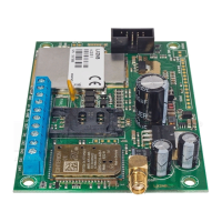
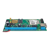
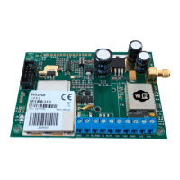
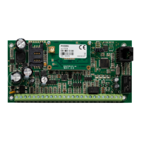
According to the above figure terminals of transmitter shall be connected to:
The positive terminal of power supply 12-14VDC
The negative terminal of power supply. Device weight. Mutual
terminal for inputs and outputs.
Control input. Works only with dedicated LX-ZAS adapter. Used
to verify the presence of a battery attached to the power supply.
Control input. Works only with dedicated LX-ZAS adapter.
Purposed for monitoring AC power supply.
Signal inputs. For connection to control panel outputs (eg. Testing
outputs connection). GND terminal is common for all inputs.
OC type outputs. For connection to the control panel outputs (eg.
As feedback during system testing). When activating they give
mass.
Terminals to connect to alarm control panel phone communicator
Terminals to connect another transmitter (eg. working in another
GSM network)
Terminals for connecting control panel, in a place where
connection of telephone to panel is predicted
Terminals for connecting to telephone
Length of the wires connecting between the transmitter and control
panel must not exceed 3m.
Outputs OUT1 and OUT2 are OC type. Do not connect the output directly
to a positive voltage relative to the ground. Do not apply a voltage
higher than 12V. The maximum current that can be controlled, should
not be greater than 100mA.
Don’t connect power supply when GSM antenna isn’t connected, because
it can cause permanent damage of GSM modem.
The procedure for programming the transmitter (see chapter 6).
THE FOLLOWING CONNECTIONS ARE PURPOSED FOR COOPERATION
WITH LX-ZAS POWER SUPPLY. IF OTHER POWER SUPPLY APPLIED,
INPUTS SHALL BE LEFT WITHOUT WIRING.