Signal inputs. Possible connection of detectors contacts or
alarm control panel outputs. GND terminal is common for
all inputs.
After careful connections examination a battery may be connected (to +/- AKU
terminals of LX-ZAS power supply) and then power may be switched on for
transformer and programming procedure of transmitter may begin (see Chapter 6).
Manufacturer reserves the right to amend appearance of printed circuit
with no effect on functionality of device.
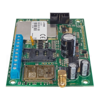
3.1.1. Wireless module antenna connector
LX2NB-5R included one internal antenna. It is also possible to connect an external
dipole type.
433MHz internal antenna
Internal antenna can be used wherever required compact size and antenna provides
appropriate coverage level detectors. Ending of the internal antenna without
isolation should be mounted in hot pole of the socket described as ANT (the right
side)
NOTE: If the device is housed in a metal box, you should not use the internal
antenna.
Figure 2. 433MHz internal antenna
433MHz external antenna dipol type