3.2 TUNING SUGGESTIONS
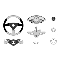
This setup might suit a driver with a light touch that races primarily tight road courses. This
offers a short throw lightly sprung steering action which will get you through chicanes quickly
all while maintaining optimal hand position for the accessory buttons at full lock. A light spring
setting reduces driver fatigue for those competing in full-length races. With reduced pressure
you can maintain precision cornering technique on the 190th lap without the sloppiness that
can come from muscle fatigue. With light spring settings, the FLDS will provide primary
resistance for wheel movement.
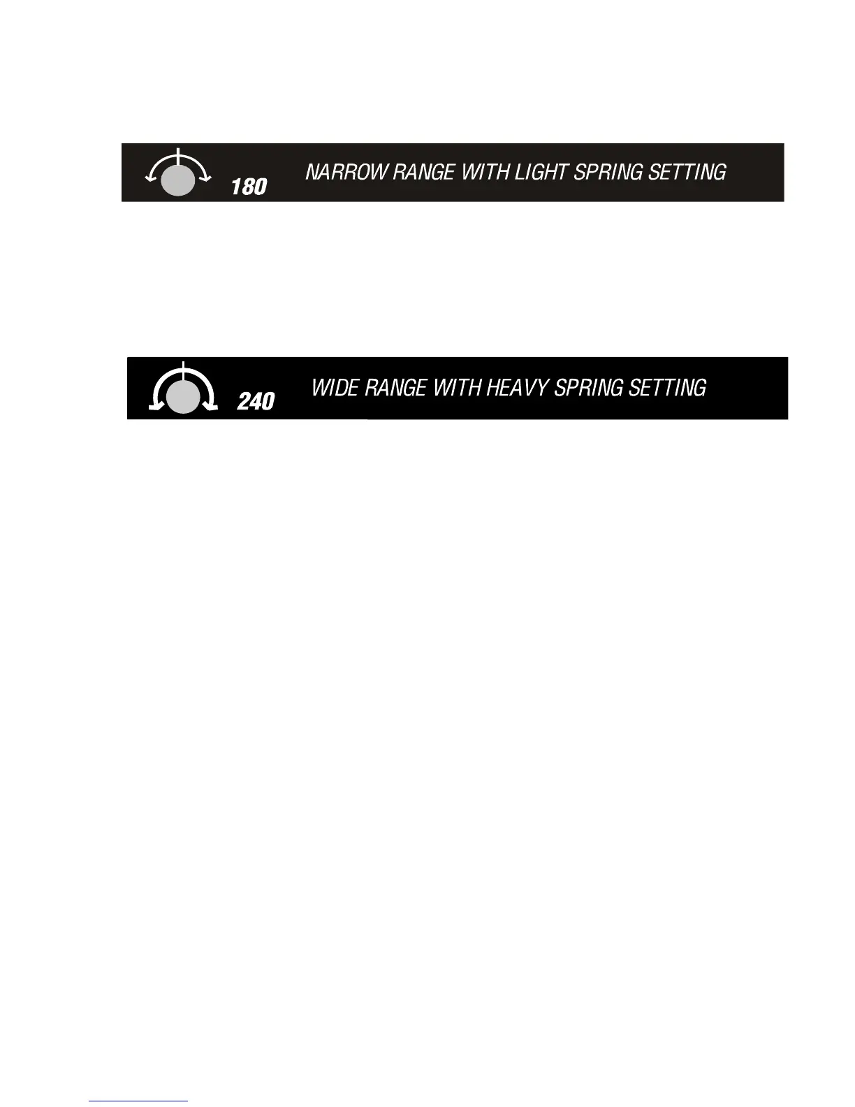
A driver running ovals might prefer more resistance and travel. A wide range of travel can
offer more fine steering adjustment in long sweeping corners, or could be set up for more pit
lane maneuverability. Up to 240 degrees or travel is available with the Trackstar 6000. With
heavier spring settings the role of FLDS is reduced. Most drivers will prefer moderate to light
spring settings when using an FLDS equipped system.
3.3 STEERING LOCK ADJUSTMENT
Four positions of steering lock are available: 180, 200, 220, and 240 degrees. The default
factory setting is 240. This adjustment should be performed first before other changes to
steering resistance are contemplated.
1 Loosen the eight screws that attach the steering unit cover to the chassis. Then remove
the cover exposing the mechanism.
2 Loosen the locknut on the preload adjusting screw underneath the steering unit, directly
below the springs [Figure 21]. Turn the adjusting screw counterclockwise until the spring
pack is loosened.
3 Grasp the top of the spring pack and pull it out from underneath the pressure arm.
Remove the springs and spring retainers from the unit.
4 Locate the wheel travel limiter [Figure 26], a disk-shaped element close to the main
chassis structural plate. Rotate the steering wheel 90 degrees to the left. The two
retaining screws for the left-hand travel adjuster stop will now be accessible. Using the
supplied 3/32" hex key, loosen and remove the 2 screws and position the stop as
desired, rotating the wheel as required to provide access. The positions are explained in
Figure 23.
5 Next tighten the screws. Repeat the adjustment as described above for the right-hand
travel adjuster stop, making certain that the adjuster is moved exactly the same amount
as the left-hand stop.
6 Reinstall the spring set following steps 4-6 in the following section.