3 WARNING! Do not exceed the maximum number of turns listed in the table for the
combination of springs being used – excessive preload pressure WILL damage the
steering camshaft and is considered MISUSE. This is NOT covered under warranty!
4 Tighten the preload adjuster locknut, while holding the preload adjuster screw in position.
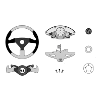
3.6 FLDS - FLUID DAMPED STEERING
The FLDS system uses a belt driven rotary fluid damper [Figure 26]. For each wheel rotation
the damper will rotate multiple times. ECCI provides each unit with the pulley ratio best suited
for the steering wheel diameter ordered. Some users may wish to reduce or increase the
amount of damping. Pulleys are color-coded for legibility. ECCI offers alternative pulleys in
several different ratios [Figure 27].
Generally, someone who uses many rapid wheel movement corrections while driving may
prefer a lighter pulley, while someone using very steady measured wheel movements may
prefer even heavier damping. Steering wheel diameter also has an effect on damping force.
Diameters smaller than the standard 13-1/2 inch wheel will create less leverage on the
steering shaft. This will increase the level of damping perceived by the driver. A heavy pulley
with a small diameter wheel like a Momo will provide a very high level of damping resistance.
ECCI units have a very different feel than other driving systems and there is a period of user
acclimation needed before getting best results from such adjustments.
3.7 SHIFT PADDLE ADJUSTMENT
The Trackstar 6000 unit is provided with Formula-1 style behind-the-wheel paddles to perform
gear shift functions. The paddles have a short throw to make rapid and reliable shifting
possible. This throw is adjustable, but the original factory setting is designed to provide the
proper amount for consistent switch actuation. If you encounter shifting anomalies, like failed
trigger inputs or double-shifting, the cause could be either a failing button or drifting outside of
proper throw adjustment.
Paddle throw is set by throw limiter stops, which constrain the movement of the paddle levers
within their limits. All ECCI paddle sets have their initial at-rest position established by set-
screws accessed from the back of the paddle set.
If adjustment is needed, boot up your computer and go to the Game Controllers module in the
Control Panel. The test window has indicators that light up when a paddle button is
depressed. Loosen the 3/8” lock nut and turn the set screw in until it activates the button
indicator light, then back off. Proper at-rest button position is set by positioning the set screw
one-third turn back from the point of button actuation. Then tighten the lock nut.
Set maximum paddle lever throw to provide a visual gap of about 0.5mm from the paddle
button surface to the face of the paddle lever. This gap is needed to assure reliability of
multiple inputs like rapid downshifts. On Momo paddles, look for similar adjusters accessible
from the front of the paddle set. Non-Momo paddle sets have set screws set into the paddle
levers themselves and accessed from the back of the paddles.
Momo wheel equipped units are provided with additional adjustability. Special two-piece
paddle levers are provided that allow for adjustment for distance in depth from the wheel rim.
Refer to Figure 28 for an illustration of how to adjust this distance.