15
Designed in
Summerville, SC
Support: Support.Eccotemp.com Shop Online: www.Eccotemp.com Phone: 866-356-1992
14
14
Support: Support.Eccotemp.com Shop Online: www.Eccotemp.com Phone: 866-356-1992
PLEASE NOTE: SH12
-
A IS FOR INDOOR PERMANENT INSTALLATIONS ONLY. THIS MANUAL AND ALL ECCOTEMP CONTENT IS SUBJECTED TO CHANGE WITHOUT NOTICE.
PLEASE VISIT SUPPORT.ECCOTEMP.COM FOR MORE INFORMATION.
English
Installation
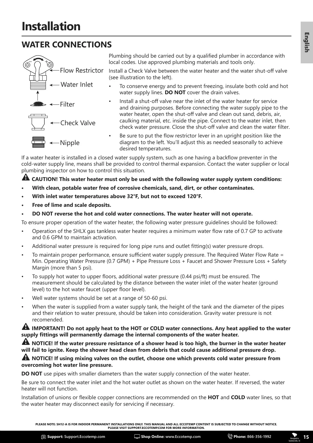
WATER CONNECTIONS
Flow Restrictor
Water Inlet
Filter
Check Valve
Nipple
Plumbing should be carried out by a qualied plumber in accordance with
local codes. Use approved plumbing materials and tools only.
Install a Check Valve between the water heater and the water shut-o valve
(see illustration to the left).
• To conserve energy and to prevent freezing, insulate both cold and hot
water supply lines. DO NOT cover the drain valves.
• Install a shut-o valve near the inlet of the water heater for service
and draining purposes. Before connecting the water supply pipe to the
water heater, open the shut-o valve and clean out sand, debris, air,
caulking material, etc. inside the pipe. Connect to the water inlet, then
check water pressure. Close the shut-o valve and clean the water lter.
• Be sure to put the ow restrictor lever in an upright position like the
diagram to the left. You’ll adjust this as needed seasonally to achieve
desired temperatures.
If a water heater is installed in a closed water supply system, such as one having a backow preventer in the
cold-water supply line, means shall be provided to control thermal expansion. Contact the water supplier or local
plumbing inspector on how to control this situation.
CAUTION! This water heater must only be used with the following water supply system conditions:
• With clean, potable water free of corrosive chemicals, sand, dirt, or other contaminates.
• With inlet water temperatures above 32°F, but not to exceed 120°F.
• Free of lime and scale deposits.
• DO NOT reverse the hot and cold water connections. The water heater will not operate.
To ensure proper operation of the water heater, the following water pressure guidelines should be followed:
• Operation of the SHLX gas tankless water heater requires a minimum water ow rate of 0.7 GP to activate
and 0.6 GPM to maintain activation.
• Additional water pressure is required for long pipe runs and outlet tting(s) water pressure drops.
• To maintain proper performance, ensure sucient water supply pressure. The Required Water Flow Rate =
Min. Operating Water Pressure (0.7 GPM) + Pipe Pressure Loss + Faucet and Shower Pressure Loss + Safety
Margin (more than 5 psi).
• To supply hot water to upper oors, additional water pressure (0.44 psi/ft) must be ensured. The
measurement should be calculated by the distance between the water inlet of the water heater (ground
level) to the hot water faucet (upper oor level).
• Well water systems should be set at a range of 50-60 psi.
• When the water is supplied from a water supply tank, the height of the tank and the diameter of the pipes
and their relation to water pressure, should be taken into consideration. Gravity water pressure is not
recomended.
IMPORTANT! Do not apply heat to the HOT or COLD water connections. Any heat applied to the water
supply ttings will permanently damage the internal components of the water heater.
NOTICE! If the water pressure resistance of a shower head is too high, the burner in the water heater
will fail to ignite. Keep the shower head clean from debris that could cause additional pressure drop.
NOTICE! If using mixing valves on the outlet, choose one which prevents cold water pressure from
overcoming hot water line pressure.
DO NOT use pipes with smaller diameters than the water supply connection of the water heater.
Be sure to connect the water inlet and the hot water outlet as shown on the water heater. If reversed, the water
heater will not function.
Installation of unions or exible copper connections are recommended on the HOT and COLD water lines, so that
the water heater may disconnect easily for servicing if necessary.