17
Designed in
Summerville, SC
Support: Support.Eccotemp.com Shop Online: www.Eccotemp.com Phone: 866-356-1992
16
16
Support: Support.Eccotemp.com Shop Online: www.Eccotemp.com Phone: 866-356-1992
PLEASE NOTE: SH12
-
A IS FOR INDOOR PERMANENT INSTALLATIONS ONLY. THIS MANUAL AND ALL ECCOTEMP CONTENT IS SUBJECTED TO CHANGE WITHOUT NOTICE.
PLEASE VISIT SUPPORT.ECCOTEMP.COM FOR MORE INFORMATION.
English
Installation
RELIEF VALVE
NOTICE! Local codes govern the installation of relief valves. If local codes require that a temperature
and pressure relief valve should be installed the manufacturer recommends a type 40XL Watts T&P relief
valve or an equivalent model be used.
NOTICE! Manual operation of relief valves should be performed at least once a year. Turn o the
electrical power and gas shut-o valve. Lift and release lever on the relief valve and check the manual
operation of the relief valve. You should take precaution to avoid contact with the hot water coming out
of the relief valve and to prevent water damage.
NOTICE! If the relief valve on the system discharges periodically, this may be due to thermal expansion
in a closed water supply system. Contact the water supplier or local plumbing inspector on how to correct
this situation. Do not plug or stopper the relief valve.
A new pressure relief valve, complying with the Standard for Relief Valves and Automatic Gas Shut-O
Devices for Hot Water Supply Systems, ANSI Z21.22, must be installed at the hot water outlet connection
of the water heater at the time of installation. Local codes shall govern the installation of relief valves.
For safe operation of the water heater, be sure that:
• The pressure rating of the relief valve must not
exceed 150 psi, the maximum working pressure of
the water heater as marked on the rating plate.
• The BTUH rating of the relief valve must equal
or exceed the BTUH input of the water heater as
marked on its rating plate.
• No valve of any type should be installed between
the relief valve and water heater.
• Discharge from the relief valve should be piped
to a suitable drain to eliminate potential water
damage. Piping used should be of a type approved
for the distribution of hot water.
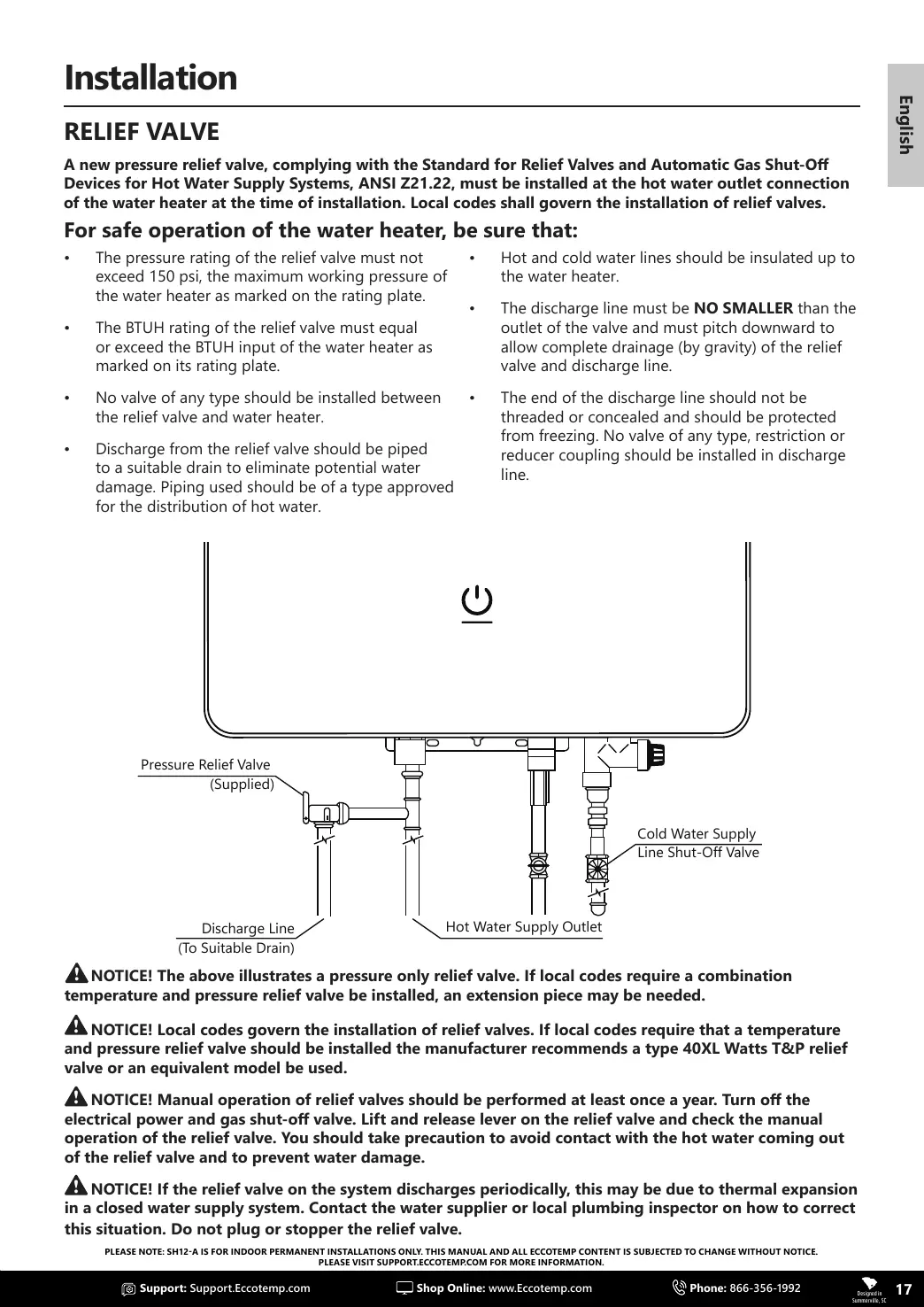
Cold Water Supply
Line Shut-Off Valve
Discharge Line
(To Suitable Drain)
Pressure Relief Valve
(Supplied)
Hot Water Supply Outlet
NOTICE! The above illustrates a pressure only relief valve. If local codes require a combination
temperature and pressure relief valve be installed, an extension piece may be needed.
• Hot and cold water lines should be insulated up to
the water heater.
• The discharge line must be NO SMALLER than the
outlet of the valve and must pitch downward to
allow complete drainage (by gravity) of the relief
valve and discharge line.
• The end of the discharge line should not be
threaded or concealed and should be protected
from freezing. No valve of any type, restriction or
reducer coupling should be installed in discharge
line.