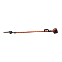
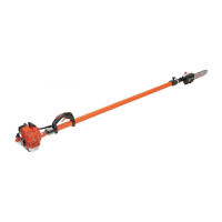
Power Pruner™
oPerator's Manual
11
1. OPERATOR'S MANUAL - Read and understand this manual before operation. Keep manual in a safe location for
future reference, i.e., operation, maintenance, storage and specications.
2. POWER HEAD - Includes the Engine, Clutch, Fuel System, Ignition System and Starter.
3. REAR HANDLE ASSEMBLY - Sturdy handle for right hand placement. Includes stop switch and throttle trigger.
4. THROTTLE TRIGGER LOCKOUT - This lever must be depressed before throttle trigger can be operated.
5. THROTTLE TRIGGER - Spring loaded to return to idle when released. During acceleration press trigger gradu-
ally for best operating technique.
6. STOP SWITCH - Mounted on top of handle assembly. Move switch forward to run, back to stop.
7. LOWER SHAFT TUBE - Durable berglass mesh housing.
8. AUTOMATIC OILER ASSEMBLY - Self oiling. Use high quality, low viscosity, non detergent bar and chain oil.
9. SAW CHAIN - 90 SG 9.53 mm low prole Oregon® saw chain. Runs approximately 610 m/min at full throttle.
10. GUIDE BAR - 305 mm guide bar.
11. CUTTING SHOE - Used to capture and stabilize branch while cutting. Place cutting shoe against branch, acceler-
ate and lower saw chain into branch.
12. CUTTING ATTACHMENT - Sealed, gear ratio is 1.5 : 1 reduction.
13. ARM REST - Provides arm rest during operation and protects arm from hot engine.
14. MUFFLER, SPARK ARRESTER - The mufer controls the exhaust noise while the spark arrester prevents hot,
glowing particles of carbon from leaving the mufer where they could possibly start a re.
15. RECOIL STARTER - Pull recoil handle slowly until starter engages, then quickly and rmly. When engine starts
return handle slowly. DO NOT let handle snap back or damage will occur.
16. FUEL TANK - Contains fuel and fuel lter.
17. FUEL TANK CAP - For closing the fuel tank.
18. CHOKE - Located above air cleaner housing. Controls operation of choke. Move lever to start position (Close
Choke) and back to run position (Open Choke).
19. PURGE BULB - Pump purge bulb until fuel is visible and ows freely in the “Clear” fuel return line. Pump bulb an
addition 4 or 5 times.
20. AIR CLEANER ASSEMBLY - Contains replaceable air lter element.
21. SPARK PLUG - Provides spark to ignite fuel mixture.
22. GUIDE BAR COVER - Used to cover guide bar and saw chain during transport and storage. Remove guide bar
cover before using unit.
23. SHOULDER HARNESS - An adjustable strap that suspends the unit from the operator.
 Loading...
