Power Pruner™
oPerator's Manual
13
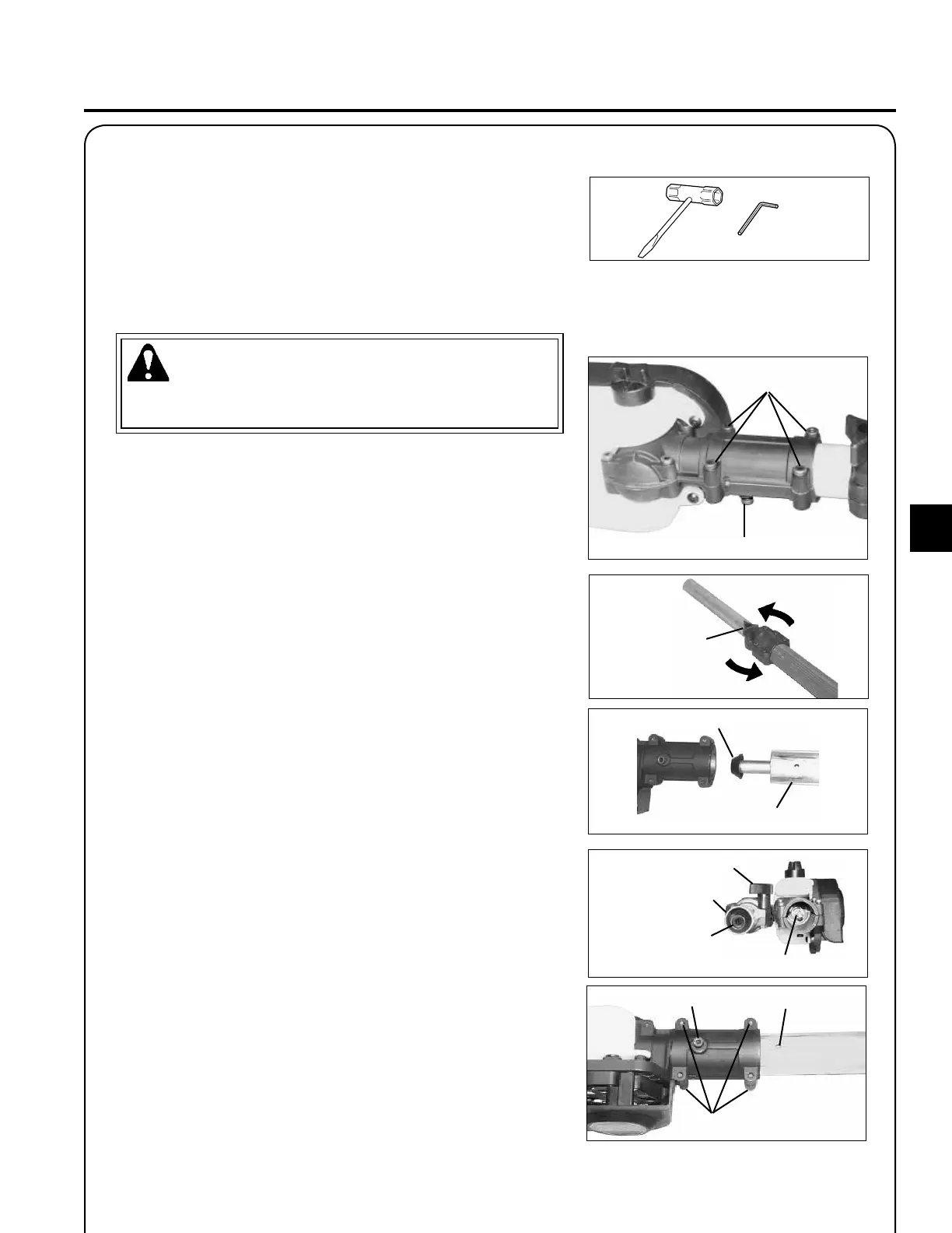
assembly
Locater bolt
WARNING
Saw Chain is sharp! Always wear gloves when handling assembly,
otherwise serious personal injury may result.
1. Loosen the four (4) bolts and remove locater bolt on cutting attach-
ment.
cuttIng attachment to shaft tube InstallatIon
Four bolts
2. Loosen center clamp knob turning anticlockwise.
3. Pull upper shaft tube out of berglass lower shaft tube 130 to 150
mm, then slide back upper shaft tube into berglass lower shaft
tube exposing inner power transmission shaft. Align and join star
shaped drive end of inner power transmission shaft with cutting
attachment shaft.
4. Align ridges on upper shaft tube with seams in cutting attachment.
5. Slide together aligning locater bolt in cutting attachment with
locating hole in upper shaft tube.
6. Install and tighten locater bolt. Tighten four (4) cutting attachment
bolts.
7. Extend upper shaft tube to desired length. Tighten center clamp
knob turning clockwise.
Clamp knob
Transmission shaft
Four bolts
Upper shaft tube
Clamp knob
Transmission shaft
Upper shaft tube
Attachment shaft
Locating
hole
Locater bolt
Tools Required: 10 x 19 mm T-Wrench, 4 mm Hexagonal Wrench
Parts Required: Power Head/Shaft Tube Assembly,
Cutting Attachment