Do you have a question about the Echo SRM-225 and is the answer not in the manual?
Contains specifications and information for safety, operation, maintenance, storage, and assembly specific to this product.
Explains possible hazards and measures to take for safe operation.
Genuine ECHO parts are available from authorized dealers. Have Model and Serial Numbers ready when ordering.
Product servicing during warranty must be performed by an Authorized ECHO Service Dealer. Contact for nearest dealer.
Contact Consumer Product Support for assistance with application, operation, or maintenance. Know model and serial number.
Register online for trouble-free warranty coverage and direct contact for updates or recalls.
Available from ECHO dealer or online. Check website for updated information. Safety videos also available.
Explanation of safety alert symbols (DANGER, WARNING) and key words indicating hazard levels.
Explains CAUTION symbol for minor/moderate injury and NOTICE for unit protection.
Identifies common symbols used on the product and their meanings, including warnings and adjustments.
Details symbols for avoiding kickout, fuel handling, choke control, and keeping clear of blades.
Warning about using E10 fuel and the importance of correct ethanol percentage for engine health.
Operator condition, eye, hand, hearing, breathing protection, and proper clothing are essential for safety.
Wear snug-fitting, durable clothing, long pants, long sleeves, and sturdy shoes. Avoid loose items.
Do not wear shorts, ties, scarves, jewelry, or open-toed shoes. Keep clothing buttoned and tucked.
Machine generates EMF. Consult physician if you have a pacemaker before operating.
Prolonged exposure to cold/vibration can cause injury like Raynaud's Phenomenon. Follow precautions.
Keep body warm, maintain circulation, limit hours, and consult physician for symptoms of cold/vibration exposure.
Overuse can cause soreness, swelling, numbness, or Carpal Tunnel Syndrome (CTS). Vibration may contribute.
Avoid awkward wrist positions, take breaks, reduce force, strengthen muscles, and seek medical help for symptoms.
DANGER: Overhead wires and engine exhaust are hazardous. Operate only in well-ventilated areas.
Clear work area, maintain firm grip and solid stance to prevent accidents and falls.
Keep exhaust area clear of flammable debris. Avoid contact during and after operation.
Use only ECHO attachments. Check unit for loose parts, damaged shields, or loose cutting attachments.
WARNING: Moving parts can amputate fingers. Stop engine, disconnect spark plug before servicing.
WARNING: Periodically check fuel system for leaks. Do not use if leaks are found. Have repaired by dealer.
Information on engine modification (EM) and catalytic converters (TWC) for emissions control.
Details on emission compliance periods and regulations for US EPA and California.
Label located on engine providing emission family and compliance period details.
Locate and understand safety decals. Order replacements if illegible. See parts ordering for details.
Details safety warnings and instructions on the shaft label, including language options and prohibitions.
Indicates hot surfaces on the unit, requiring caution to avoid burns.
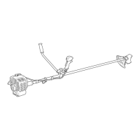
Detailed description of components like Power Head, Throttle Handle, Stop Switch, Support Handle, Drive Shaft, and Recoil Starter.
Detailed description of components like Muffler, Fuel Tank, Fuel Tank Cap, Choke, Air Cleaner, and Purge Bulb.
List of items included in the package: Power Head/Drive Shaft, manuals, warranty, safety glasses, and oil sample.
Instructions for installing the debris shield with cutoff knife for nylon line operation only. Warning against using without cutoff knife for blades.
Parts required and caution about sharp cutoff knife and hot gearcase during nylon line head installation.
Detailed steps for attaching the nylon line head, including locking tool usage and notice about debris shield.
Instructions on how to advance trimmer line by tapping the head against the ground.
Steps for removing nylon line head and positioning support handle for comfortable operation.
Warnings about moving parts and hazardous engine exhaust position.
WARNING: Sparks may start fires in dry vegetation. Unit has spark arrestor. Contact local fire authorities.
WARNING: Blade use requires specific Brush Cutter configuration (shield, handle, harness). Incorrect setup can cause injury.
Table listing required parts (handle, shield, harness, plates, nuts, pins) for different blade types.
WARNING: DO NOT INSTALL BLADES ON GT (CURVED SHAFT) MODELS. Check arbor diameter and use new cotter pin.
Harness for heavy cutters. Barrier Bar restricts movement but is not a handle.
WARNING: Match blade to material. Blades must be sharp. Dull blades increase kick-out risk.
Details on Plastic/Nylon, 8-Tooth, 80-Tooth, and 22-Tooth blades and their intended uses.
Recommended for all trimmer/brush cutter use to reduce operator fatigue and improve safety during blade operation.
WARNING: Do not use diesel or alternative fuels (E15, E85, methanol). May cause damage, poor performance, or failure.
Use 89 Octane unleaded gasoline and ISO-L-EGD/J.A.S.O. FD certified oil. Incorrect oil voids warranty.
Echo premium Power Blend X™ oil may be mixed at 50:1 for all Echo engines regardless of older manual ratios.
DANGER: Fuel is very flammable. Use approved containers, no smoking/flames near fuel, loosen caps slowly.
Step-by-step guide for mixing gasoline and 2-stroke oil at a 50:1 ratio, with US and Metric measurements.
Do not store with fuel in tank. Return unused fuel to approved container. Store fuel in approved container.
Stored fuel ages. Do not mix more fuel than needed for 30/90 days. Shake fuel container before use.
WARNING: Keep movable parts clear. Move stop switch to RUN. Adjust choke, pump purge bulb, use recoil starter.
Steps for choke (COLD START/RUN), purge bulb, and recoil starter operation for cold starts.
Same as Cold Start but do not close choke. Warning: attachment should not move at idle.
Steps for warm start: move stop switch to RUN, pump purge bulb, use recoil starter.
If attachment moves at idle after adjustment, readjust carburetor or see dealer.
Release throttle to idle, then move stop switch to STOP position. Warning if switch fails.
WARNING: Moving parts can cause severe injury. Wear gloves. Allow unit to cool before servicing.
Defines Level 1 (Easy) and Level 2 (Moderate difficulty) for maintenance tasks.
Chart detailing maintenance tasks, procedures, and required skill levels for daily, every refuel, 3-month, and yearly checks.
Intervals are maximums; actual use determines frequency. Notes on grease application and fuel tanks.
Level 1 task. Steps to close choke, remove cover, clean/replace filter, and install cover.
Level 1 task. DANGER: Fuel is flammable. Steps to remove loose dirt, pull filter, and install new filter.
Level 2 task. Use specific plug type. Steps to remove, clean/replace, adjust gap, and tighten.
Level 2 task. Ensure cooling fins are clear for proper airflow and heat dissipation. No specific parts required if careful.
Steps to remove engine cover, use brush to clean cylinder fins, and remove ignition wires from clip.
NOTICE: Do NOT use a metal scraper to remove dirt from cylinder fins. Avoid scratching.
Level 2 task. Steps to remove engine cover, piston at TDC, remove screen, clean, and replace if damaged.
Level 2 task. Clean deposits from exhaust port using appropriate materials.
Steps to remove muffler/heat shield, clean port with wood/plastic tool, inspect heat shield, and reassemble.
Level 2 task. Engine break-in required before adjustment. High altitude operation may require adjustment.
New engines require two tanks of fuel break-in before carburetor adjustments. This stabilizes performance.
NOTICE: If adjusted for high altitude, re-adjust for lower altitude to prevent severe engine damage.
Check and reset idle speed using idle speed screw if necessary. Warning: attachment must not move at idle.
Level 1 task. Requires Lithium Based Grease. Check and add grease as necessary, but do not over-fill.
Clean debris, check and add grease to gear case. Do not over-fill.
Steps to loosen screws, remove shield, pull flexible cable, wipe clean, re-coat with grease, and reassemble.
Note that disassembly is not normally needed, but provides instructions if required.
For more information scan QR code. Caution: sharp knife, hot gearcase. Steps to cut, align, and insert line.
Steps to wind line onto spool by turning knob clockwise until about 13 cm remains exposed.
NOTICE: If wear indicators are smooth or holes appear, replace cover or entire head.
Three blade styles. 8-tooth sharpens during normal maintenance. Clearing/80-tooth require professional service.
Inspect blades for cracks, missing teeth, or bending. Replace if any damage is found.
Remove equal material from each tooth for balance. Unbalanced blades cause unsafe handling and failure.
File each tooth at 30-degree angle. Do not file gullet; radius must remain. Avoid overheating teeth.
NOTICE: Use care not to overheat teeth. Do not place blade in cooling water; this changes temper and causes failure.
Check tooth radius for sharp corners. Use round file to renew radius.
Chart listing problems (no fuel, wet muffler, no spark), causes, and remedies for starting issues.
Chart listing problems (dies, won't accelerate), causes, and remedies for air filter, fuel filter, carburetor, etc.
DANGER: Fuel vapors are flammable and may cause fire/explosion. Never test spark near plug hole.
WARNING: Hot muffler/cover. Keep exhaust area clear of debris during transport or storage.
Do not store for over 30 days without protective maintenance. Store unit in a dry, dust-free place.
DANGER: Do not store in enclosure where fuel fumes may accumulate or reach an open flame or spark.
Steps include: set switch to OFF, clean unit, perform lubrication, tighten screws, drain fuel tank, add oil to cylinder.
Detailed specifications for SRM-225 model: dimensions, weight, engine, bore, stroke, displacement, exhaust, carburetor, ignition, etc.
Specifies 89 Octane gasoline, max 10% Ethanol/15% MTBE, and ISO-L-EGD/J.A.S.O. FD certified oil.
Clutch engagement speed is 3,850 RPM.
Wide Open Throttle speed is 8,700 RPM.
Blank page for user notes.
Register online for updates and warranty. Mail form if no internet access.
Form for registering product online or via mail. Collects purchaser, purchase, and usage information.
Blank page for user notes.