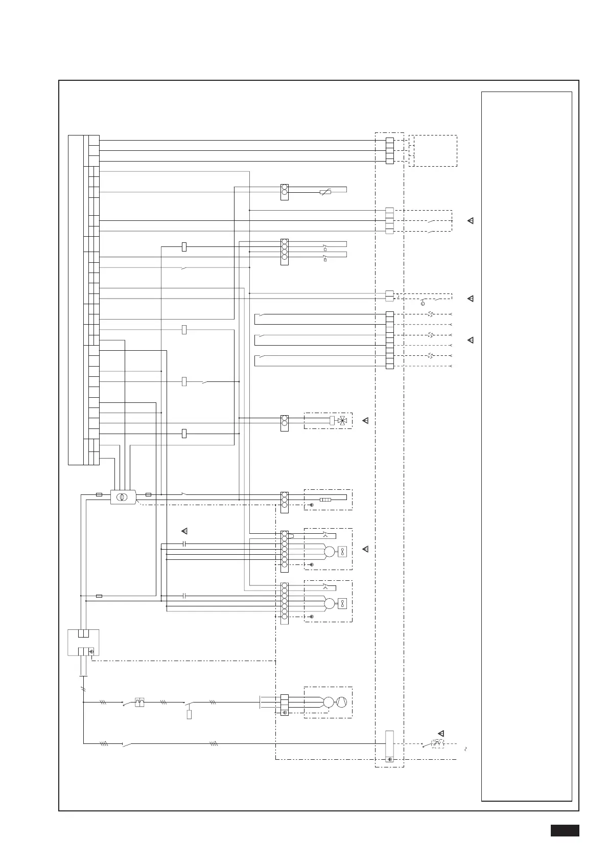
0031÷0061 THREE-PHASE WIRING DIAGRAM
Outline wiring diagram, refer to the diagram on the electrical panel of the unit.
Factory installed components
A1 Radio interference suppresser
A2 Electronic controller
A6 Unit control display keyboard
BP3 Condensation/evaporation control pressure transducer
C2-3 Fans start capacitors
EV1 Fans
F1 High pressure switch
F2 Low pressure switch
FU1 Transformer protection fuse
FU2 Control superposed circuit fuse protection
FU3 Fan fuse protection
GN1 Green light for ON compressor
KA1 High pressure switch relay
KA2 Alarm relay
KA3 Defrosting relay
KM1 Compressor contactor
QF1 Chilling assembly thermal overload switch
QM1 Compressor thermal overload switch
QS1 Door lock disconnector switch
R1 Compressor oil sump heater
RD1 Red lockout warning light
SAI On-off switch and/or timer input
SA2 Summer-winter switch input
TC1 Auxiliary circuit 12/24VAC transformer
WH1 White defrosting indicator light
YV1 Cycle reversal valve
Z1 Compressor
Attenzione:
1 Switch not included in supply
2For 0051-0061 models only
3 Heat pumps only
4 Lockout indicator light not included in supply
5 Optional ON-OFF switch and/or timer
6 Optional summer-winter switch