The units are pre-filled with a sufficient quantity of refrig-
erant for connection to the corresponding internal unit
and for a maximum pipe length of 5m.
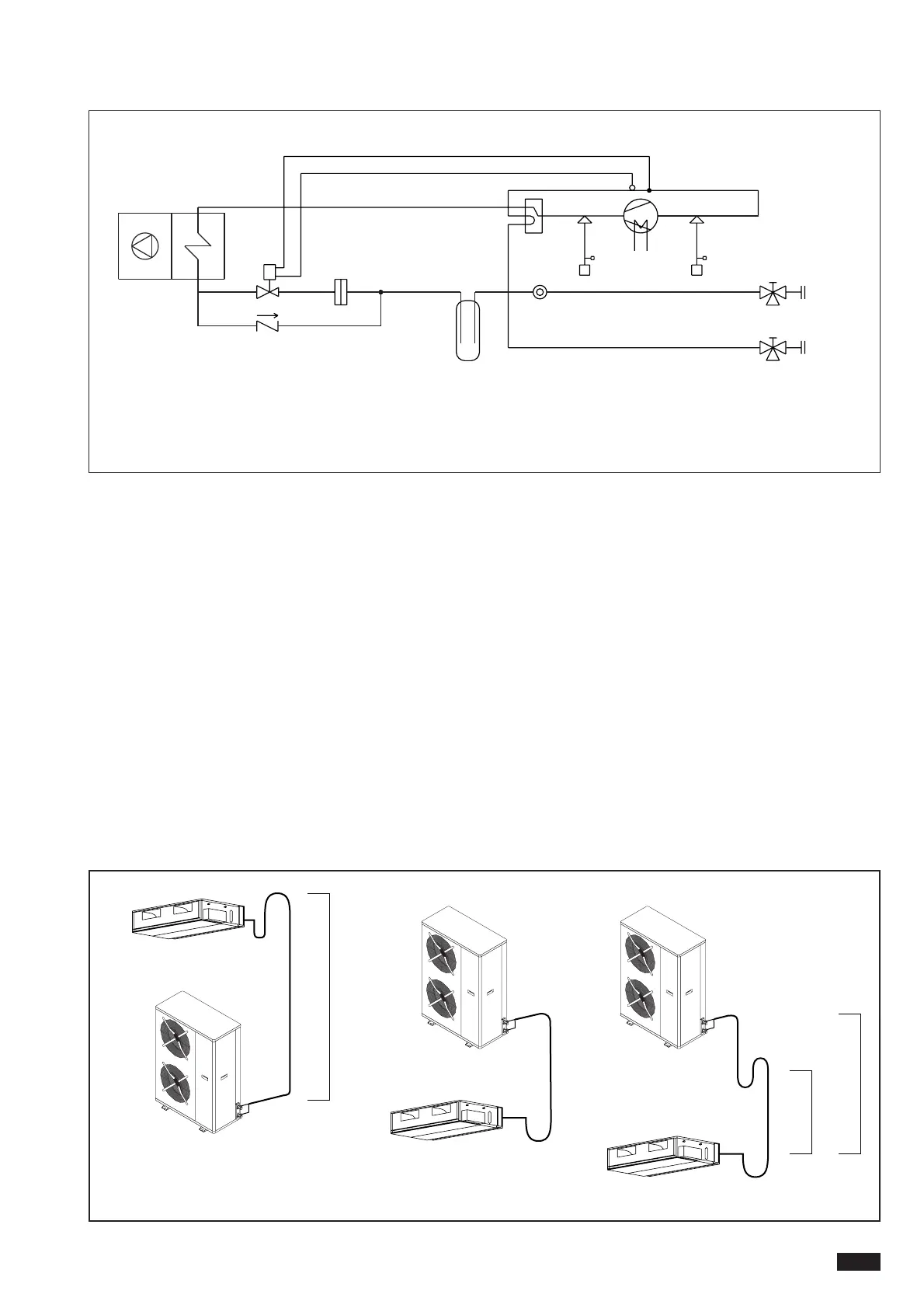
PROCEDURE FOR CORRECT CONNECTION
Intake/discharge piping
1. Insulate the piping adequately with anti-condensate
“closed cell” type polyethylene to a minimum thickness
of 9 mm.
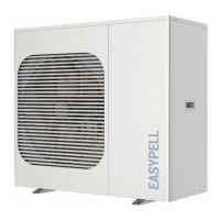
2. If the external unit is lower than the internal unit, a
siphon must be fitted to avoid fluid returning towards
the compressor (see Fig. 1).
3. If the external unit is higher than the internal unit by
less than 6m, it is sufficient to fit an air trap before the
internal unit (see Fig. 2).
4. If the external unit is higher than the internal unit by
more than 6m, an oil collection siphon should be fitted
every 6m and an air trap should be included before the
internal unit (see Fig. 3).
5. When installing the piping, make sure all bends have a
large radius.Avoid hairpins. Do not squash the pipes.
Liquid piping
1. Avoid using excessive diameters to avoid excessive
refrigerant content;
2. If the piping is exposed to heat sources, insulate it
appropriately.