Chapter 1
| Switch Description
System Overview
– 10 –
Hardware
Components
Each chapter in this manual describes related switch components together with
their installation requirements and procedures. To understand each component in
detail, refer to the relevant chapter.
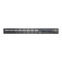
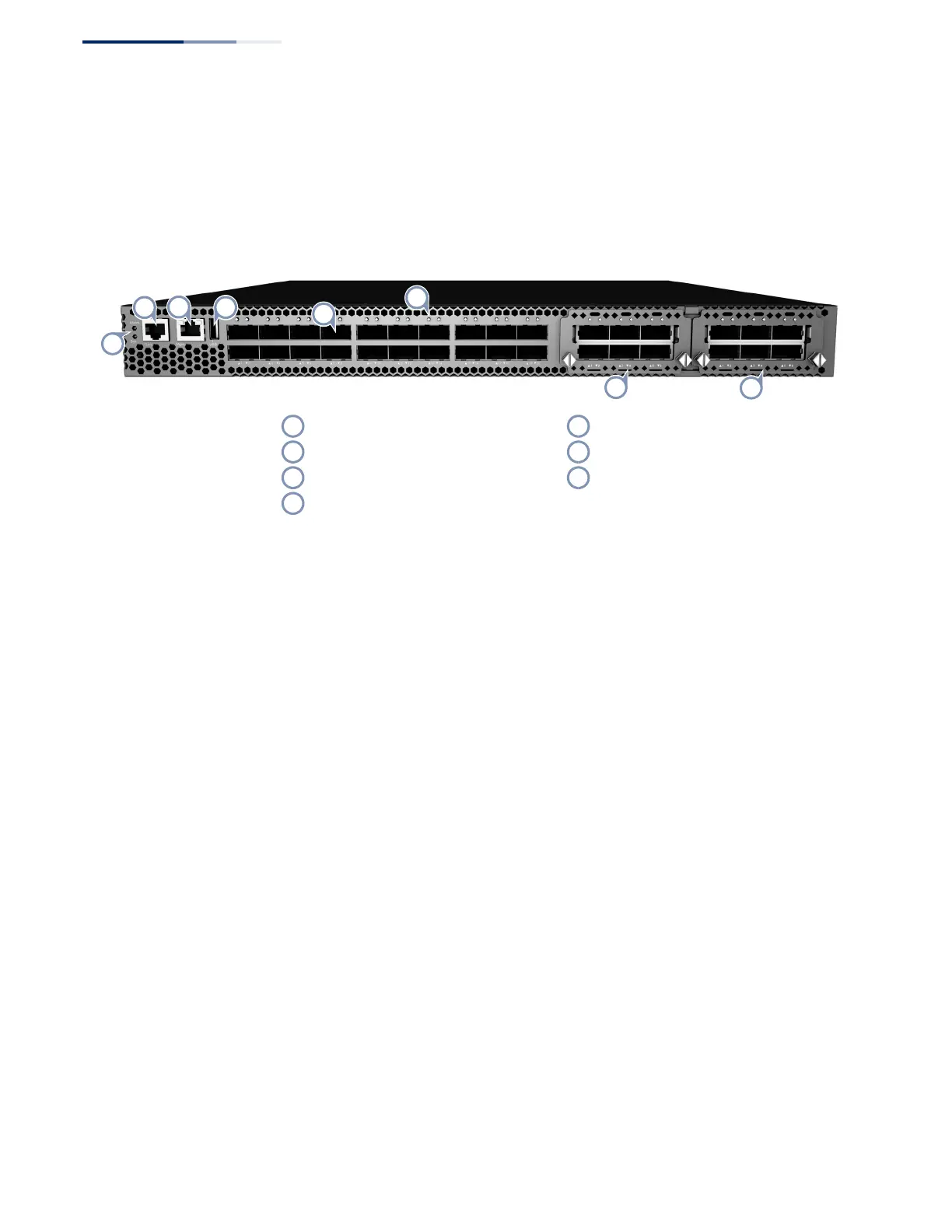
Figure 1: Front Panel with QSFP+ Expansion Modules
40G QSFP+ Slots: The switch contains 20 Quad Small Form Factor Pluggable Plus
(QSFP+) transceiver slots that operate up to 40 Gbps full duplex.
Expansion Slots: The switch contains two expansion slots that support a six-port
40G QSFP+ expansion module.
System LEDs: The switch supports indicator LEDs for displaying system status.
Port LEDs: The switch supports indicator LEDs for displaying port status.
Console Port: The RJ-45 connector on the front panel labeled “Console” provides
an out-of-band serial connection to a terminal or a PC running terminal emulation
software. The port can be used for performing switch monitoring and
configuration.
Management Port: The RJ-45 connector on the front panel labeled “Mgmt”
provides an out-of-band Ethernet connection to a management PC. The port can
be used exclusively for performing switch monitoring and configuration.
USB Port: The USB connector on the front panel labeled provides an on-site file
exchange method. The port can be used for copying configuration files to and from
the switch.
RJ-45 Console Port 40G QSFP+ Slot LEDs
Out-of-Band RJ-45 Management Port 6-port 40G QSFP+ Expansion Module
USB Slot System LEDs
40G QSFP+ Slots
 Loading...