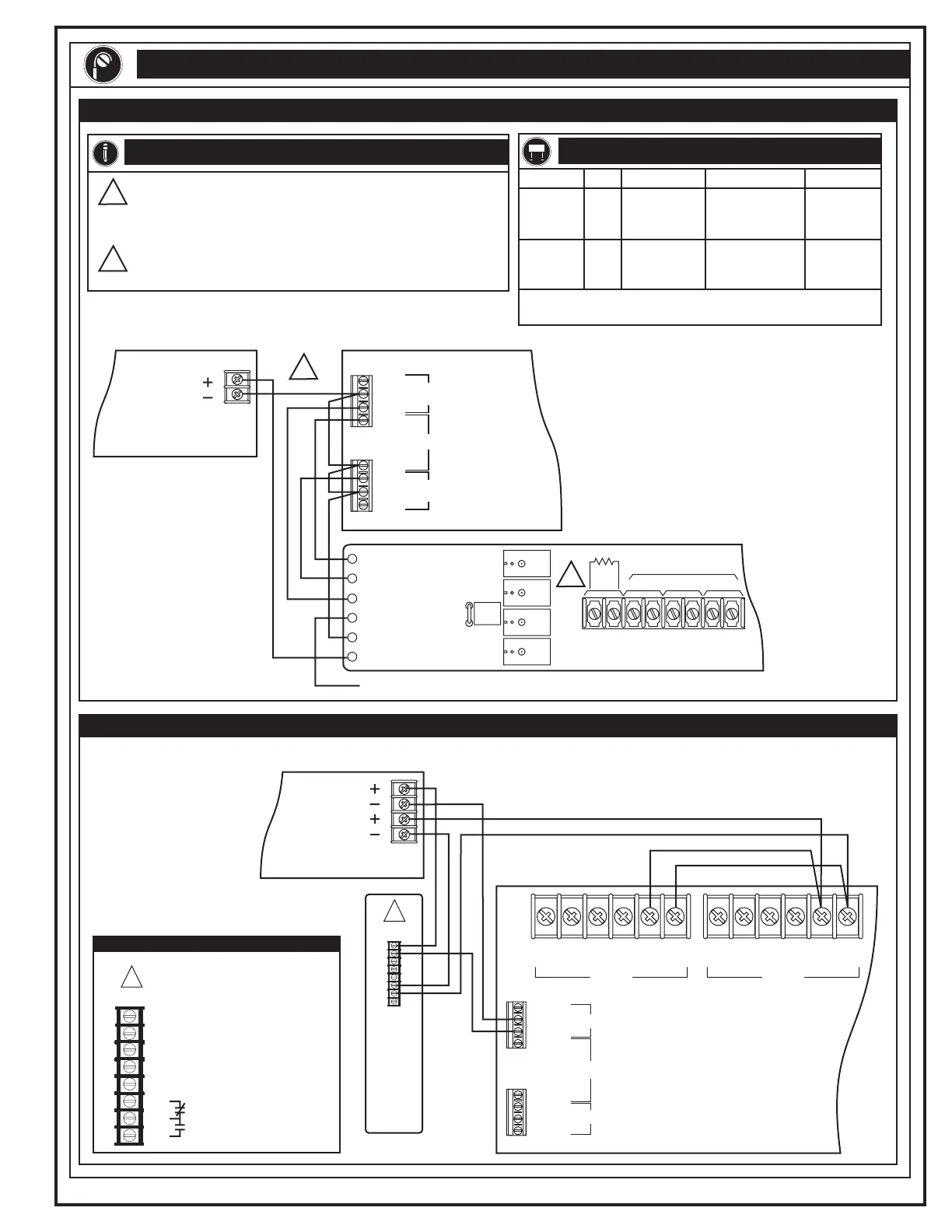
INTERNAL WIRING
MTM Wiring
270210.CDR REV 3.0 Page 3 of 4
RPM Wiring
RPM Jumper Settings
Notes
No Connection
TB4
Main Controller Module
TB5
NC
NO
COM
COM
COM
NO
NO
ALARM
SUPERVISORY
TROUBLE
NC
TB1
RPM
REVERSE POLARITY
TRANSMITTERS
CITY
BOX
ALARM
TROUBLE SUPV
SUPV
TRBL
ALRM
TRBL IN
COM
JP1
+24
12
3
4
5
6
78
2
24 Vdc
Listed Primary or
Auxiliary power supply
1
JP1
Out
In
Separate
Circuits*
*Alarm, Supervisory, and Trouble
** Alarm overrides supervisory and trouble.
Circuits*
Single
Circuit*
Alarm Supervisory Trouble
TB1-3,4:
Reverse
Polarity
TB1-3,4:
Reverse
Polarity
TB1-7,8:
Reverse
Polarity
TB1-5,6:
Reverse
Polarity
TB1-3,4:
0.0 Vdc**
TB1-3,4:
0.0 Vdc**
UL/ULC Listed 3.9 k EOL resistor (P/N 260001) required. Circuit
not used.
W
1
2
Power-limited if the source is power-limited. If the source is
nonpower-limited, maintain a space of 1/4 inch (6.4 mm) from
power-limited wiring. Otherwise, use FPL, FPLP, FPLR, or an
equivalent in accordance with the National Electric Code.
MTM
1
1
Main
Controller
Module
ALARM
SUPERVISORY
TROUBLE
NC
NC
COM
COM
COM
NO
NO
NO
SOURCE SOURCENAC1/B NAC1/BNAC1/A NAC1/A
++++++
______
TB1
TB1
Detail A
24V1
COM4
COM2
K23
K35
NC6
C7
NO8
Morse U: K2 and K3
jumpered to COM
March Time: K3
jumpered to COM
Temporal: No jumpers
Contact Ratings: 24Vdc
@ 4A (0.35 pf) pilot duty
TB1
TB2
TB4
TB5
24 Vdc
Listed Primary or
Auxiliary power supply
24 Vdc
Technical Manuals Online! - http://www.tech-man.com


 To Next Page