A344-02-880 Issue J
Page 54 © Edwards Limited 2007. All rights reserved.
Edwards and the Edwards logo are trademarks of Edwards Limited.
Appendix A
A4.1 Start-up
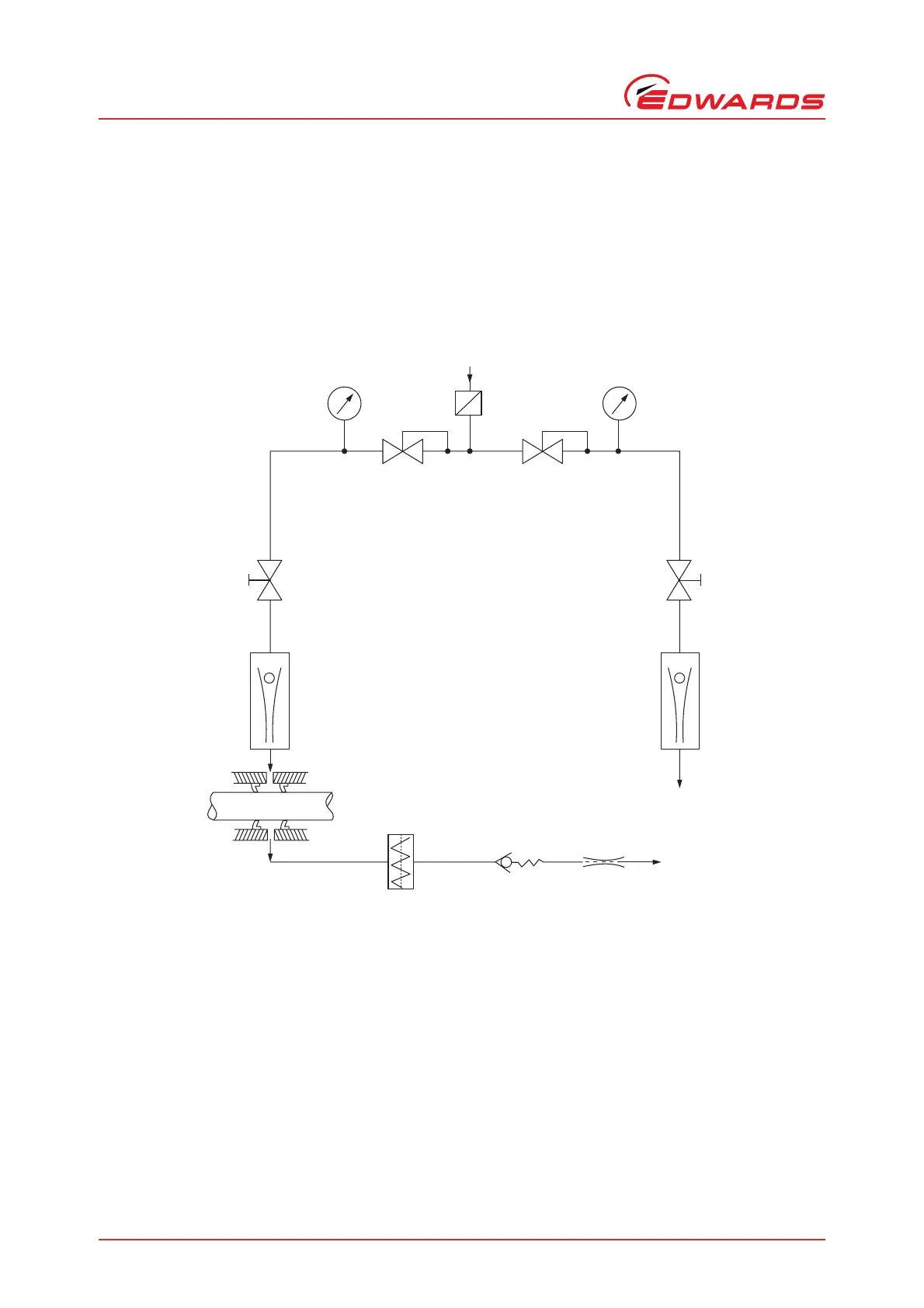
Refer to Figure A3. Before you start the pump, check the following additional points:
z Check the pressure regulator for the dry nitrogen supply to the gas-ballast solenoid and shaft-seals is set to
4psi.
z Check the pressure regulator for the dry nitrogen supply to the oil-box is set to 7 psi.
Figure A3 - Typical dry nitrogen gas circuit
2
3
1
5
8
9101112
7
6
4
AA/5013/A
1. Filtered dry nitrogen supply (~50 psi)
2. Pressure regulator (set 4 psi)
3. Pressure regulator (set 7 psi)
4. Pressure gauge (0-30 psi)
5. Flow regulator valve
6. Flow meter
7. Dry nitrogen gas to oil-box
8. Main shaft-seals
9. Solenoid valve
10. Non-return valve
11. Fixed restrictor
12. Dry nitrogen gas-ballast input