EasyManua.ls Logo

Edwards GV Series

Edwards GV Series
56 pages
To Next Page IconTo Next Page
To Previous Page IconTo Previous Page
Loading...
© Edwards Limited 2012. All rights reserved. Page 15
Edwards and the Edwards logo are trademarks of Edwards Limited.
Installation
A705-61-880 Issue M
Figure 3 - Schematic diagram of the recommended electrical connections
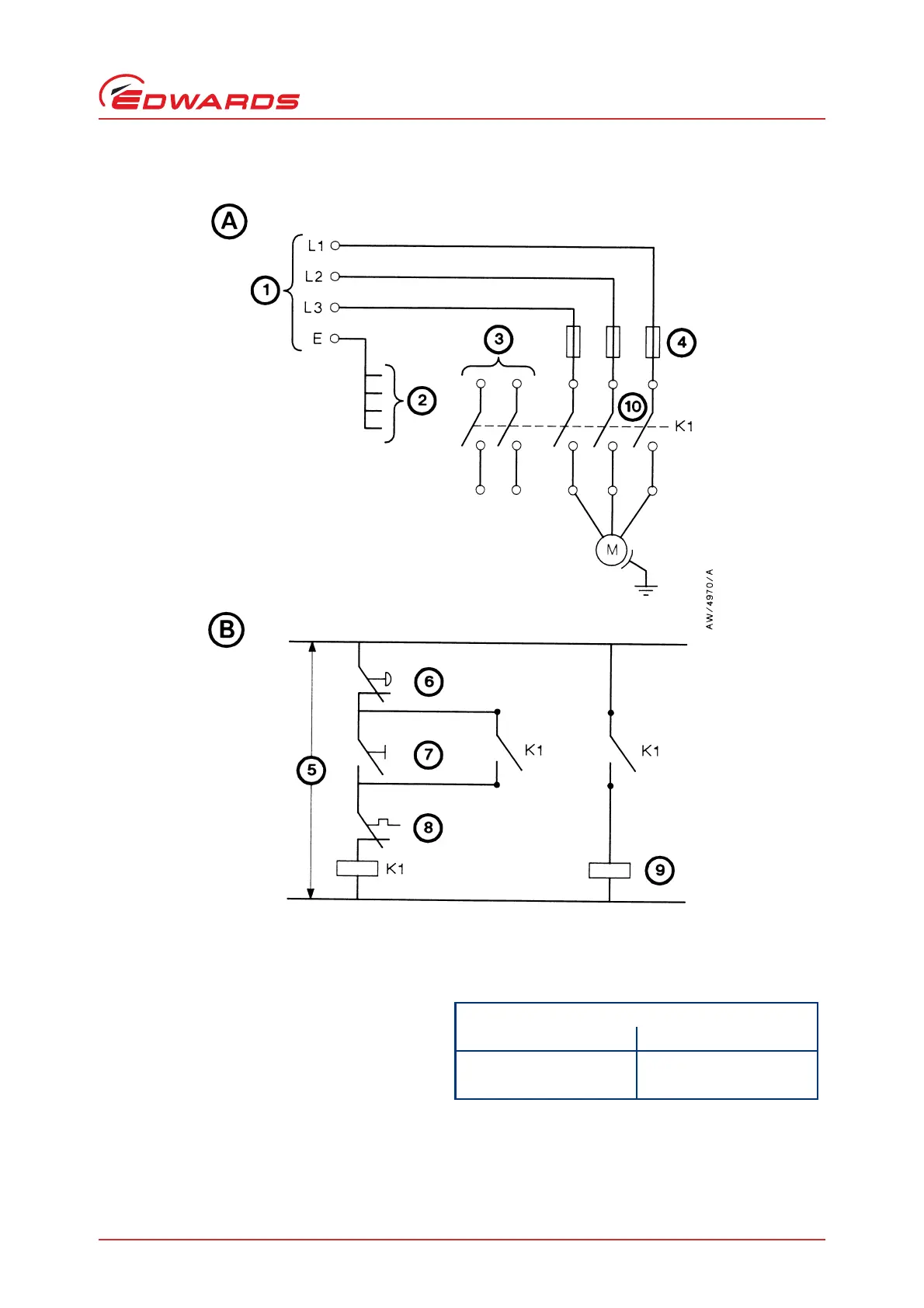
1. To your electrical supply
2. Earth (ground) points
3. Auxiliary contacts (2 off, normally closed)
4. Fuse or circuit breaker
5. Control voltage
6. Stop control
7. Start control
8. Shut-down thermal snap-switch
9. Inlet-valve control solenoid (optional)
10.Contactor
A. Pump-motor connections
B. Control circuit
Earth (ground) points
Location Size
Thermal snap-switch box M4 tapped hole
Pump-motor -

Table of Contents

Related product manuals