© Edwards Limited 2012. All rights reserved. Page 21
Edwards and the Edwards logo are trademarks of Edwards Limited.
Installation
A705-61-880 Issue M
3.11 Connect the pump-inlet
When you connect the pump to the process system:
Support process pipelines to stop the transmission of stress to pipeline joints.
Use a flexible connection in the pipeline from the process system to the pump to reduce vibration and stress
in the system pipelines.
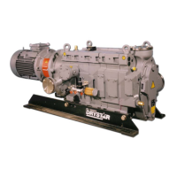
Use the following procedure to connect the inlet of the GV pump to your process system. This procedure assumes
that a mechanical booster pump has not been fitted. If a mechanical booster pump has been fitted, use the
instructions given in the appropriate instruction manual supplied with the mechanical booster pump.
1. Refer to Figure 1. Undo and remove the eight M8 x 35 hex-head bolts which secure the blanking-plate to the
pump-inlet (6) and remove the blanking-plate. Retain the bolts.
2. Use the combined trapped ‘O’ ring and mesh filter supplied to connect the pump-inlet (6) to your vacuum
system; secure with the bolts retained in Step 1.
Note: If required, you can adapt the blanking-plate removed in Step 1 above to fit your system pipelines: drill a
suitable size hole in the centre of the blanking-plate, then weld the blanking-plate to your pipeline.
3.12 Connect the pump outlet
Install an outlet catchpot to prevent the drainage of condensate back into the pump. If you do not, condensate
which drains back into the pump may damage it or cause it to seize.
Incorporate flexible bellows in the exhaust pipeline to reduce the transmission of vibration and to prevent loading of
coupling-joints. If you use flexible bellows, you must ensure that you use bellows which have a maximum pressure
rating which is greater than the highest pressure that can be generated in your system, and which can withstand the
maximum temperatures that can be generated by your process conditions.
Use the following procedure to connect the pump-outlet to your exhaust pipeline:
1. Refer to Figure 1. Undo and remove the four M8 x 50 hex-head bolts, nuts and washers which secure the
blanking-plate to the pump-outlet (12) and remove the blanking-plate. Retain the bolts, nuts and washers.
2. Use the trapped ‘O’ ring supplied to connect the pump-outlet (12) to your exhaust pipeline; secure with the
bolts, nuts and washers retained in Step 1.
Note: If required, you can adapt the blanking-plate removed in Step 1 above to fit your exhaust pipeline: drill a
suitable size hole in the centre of the blanking-plate, then weld the blanking-plate to your pipeline.
Connect the pump outlet to a suitable treatment plant to prevent the discharge of dangerous gases
and vapours to the surrounding atmosphere.

 Loading...
